Thermostat device

a technology of thermostat and thermostat, which is applied in the direction of machines/engines, process and machine control, instruments, etc., can solve the problems of large number of structural components, considerable pressure loss, and complex construction, so as to reduce the number of structural components and reduce the loss of pressure. the effect of pressure loss and pressure loss

Active Publication Date: 2006-07-27
NIPPON THERMOSTAT CO LTD
View PDF1 Cites 13 Cited by
  • Summary
  • Abstract
  • Description
  • Claims
  • Application Information

AI Technical Summary

Benefits of technology

[0014] As described above, with a thermostat device according to the present invention, by optimizing the shape of the valve seat that is further on the downstream side in the direction of flow of the cooling water than the valve seat constituted by the internal wall face forming a cooling water passage within the valve housing, pressure loss can be diminished and the flow of cooling water can thereby be optimized, making it possible to ensure the required flow rate characteristic of a thermostat device.
[0015] In particular, according to the present invention, pressure loss at the valve or valve body due to the valve seat on which this is seated is diminished, and pressure loss around the thermoelement is diminished, so flow rate control at the valve can be optimally performed and its function as a thermostat can be exhibited.
[0016] It has been confirmed by analysis and experiment that, with a thermostat devi

Problems solved by technology

However, since the conventional thermostat device of this type has a construction wherein a valve seat that seats a first valve body is provided in a part of the main body frame, the construction being such that the entire device is arranged incorporated in the fluid passage, the number of structural components is large and the construction is complicated; in addition, many portions of this device presented resistance to the fluid flow, increasing the resistance to passage of water and resulting in considerable loss of pressure, so there were problems in achieving the required

Method used


Image

  • Thermostat device
  • Thermostat device
  • Thermostat device

Examples


Embodiment Construction

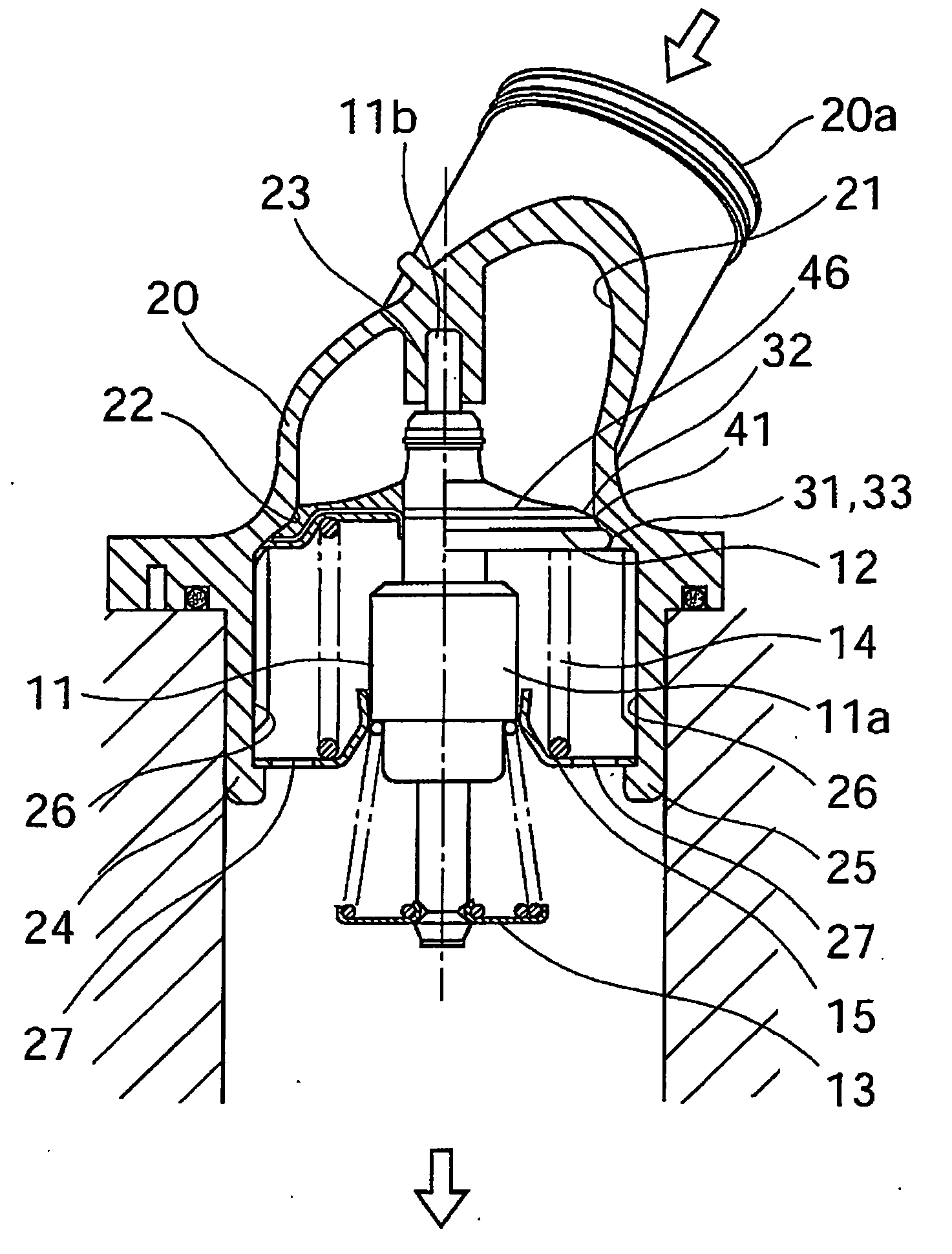
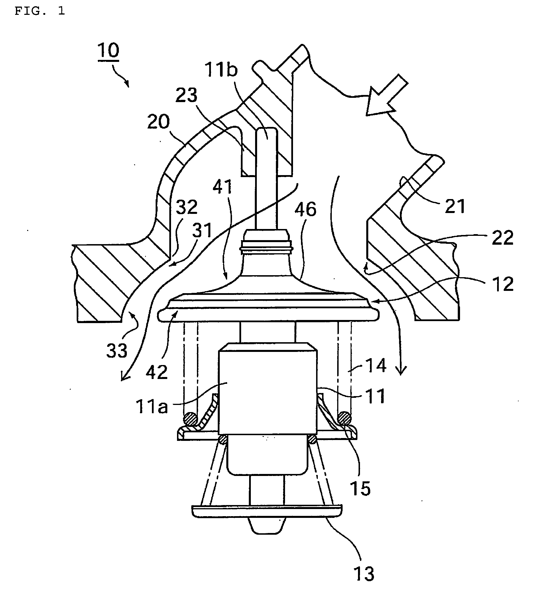
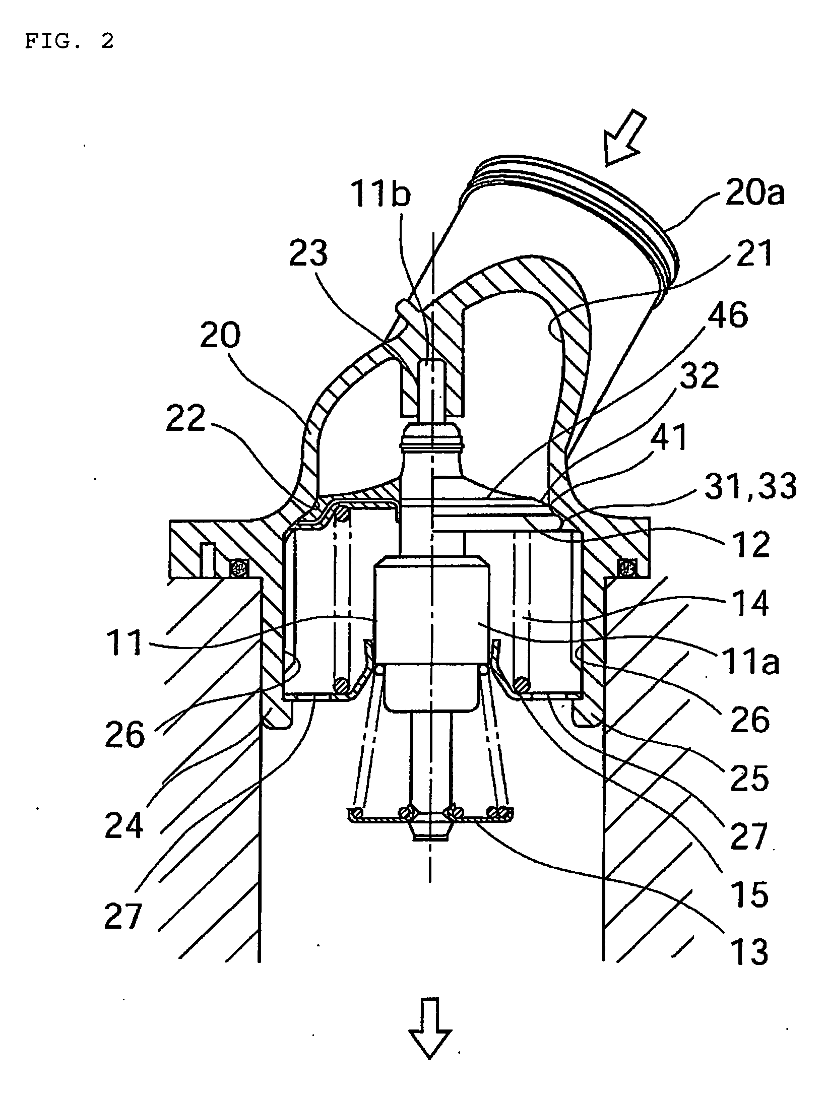
[0027]FIG. 1 to FIG. 4 show an embodiment of a thermostat device according to the present invention.

[0028] In these Figures, in a cooling system of for example an automobile engine, the thermostat device, which is a temperature sensing type automatic valve indicated by the reference symbol 10 is attached at the intersection of a cooling water channel on the radiator side and a bypass passage from the engine outlet side, and is employed for controlling the temperature of the cooling water reaching the engine inlet by selectively switching the flow of cooling water in the first and second fluid flow paths constituted by these passages.

[0029] As shown in FIG. 1 and FIG. 2, the thermostat device 10 comprises a thermoelement 11 which is the working body that is operated by a temperature change of the fluid: at one end (upper side in the Figure) of this thermoelement 11, there is provided a first valve body 12 that presents a substantially umbrella shape and at the other end (lower side...


PUM


Abstract

To optimize the valve seat shape of the valve housing such that the resistance to passage of cooling water can be diminished in a housing type thermostat device.
The valve seat shape further on the downstream side in the direction of flow of the cooling water than the valve seat 22 where an umbrella-shaped valve body 12 is seated, which is an internal wall face forming a cooling water passage 21 within the valve housing 20, is formed in a shape such that, in the valve open condition, the cross-sectional area of the passage that is formed between the inlet seal 32 of the valve seat and the top face 41 of the valve body gradually decreases on the cooling water inlet 31 side with reference to the maximum passage cross-sectional area on the upstream side in the flow direction of the cooling water, and such that the area of the passage at the face perpendicular to the top face gradually increases on the cooling water outlet 33 side so that cooling water flows along the top face of the valve body.

Description

TECHNICAL FIELD [0001] The present invention relates to a thermostat device which is a temperature sensing type automatic valve employed for control of cooling water temperature by switching the flow of engine cooling water by operating in response to temperature change of the cooling water, in a cooling water circuit of an internal combustion engine (hereinbelow called an engine) whereby cooling water that cools an engine employed in, for example, an automobile is circulated through a heat exchanger (hereinbelow referred to as a radiator), and in particular relates to a housing type thermostat device in which the main body of a thermoelement, valve body or the like is incorporated in a valve housing provided with a cooling water inlet. BACKGROUND ART [0002] In automobile engines, in order to cool these, typically a cooling system of the water-cooling type using a radiator is employed. Conventionally, in a cooling system of this type, a thermostat or the like, employing a thermally ...

Claims


Application Information

Patent Timeline
IPC IPC(8): G05D23/13G05D23/12F01P7/16F16K31/68G05D23/02
CPCF01P7/16F01P2070/00G05D23/022
Inventor INOUE, FUJIO
Owner NIPPON THERMOSTAT CO LTD
Why Eureka
Try Eureka