Method and system for scattered coincidence estimation in a time-of-flight positron emission tomography system

a positron emission tomography and scatter correction technology, applied in the field of positron emission tomography (pet) systems, can solve the problems of less than acceptable image resolution, inaccurate image of annihilation distribution,

Active Publication Date: 2006-07-27
GENERAL ELECTRIC CO
View PDF4 Cites 56 Cited by
  • Summary
  • Abstract
  • Description
  • Claims
  • Application Information

AI Technical Summary

Problems solved by technology

These algorithms, however, will produce inaccurate images of the annihilation distribution if the input data is not corrected for the occurrence of scatter coincidences in the TOF data.
However, using only a count of the number of events, or a simple scaling technique, may result in less than acceptable image resolution, particularly when imaging smaller objects.

Method used


Image

  • Method and system for scattered coincidence estimation in a time-of-flight positron emission tomography system
  • Method and system for scattered coincidence estimation in a time-of-flight positron emission tomography system
  • Method and system for scattered coincidence estimation in a time-of-flight positron emission tomography system

Examples


Embodiment Construction

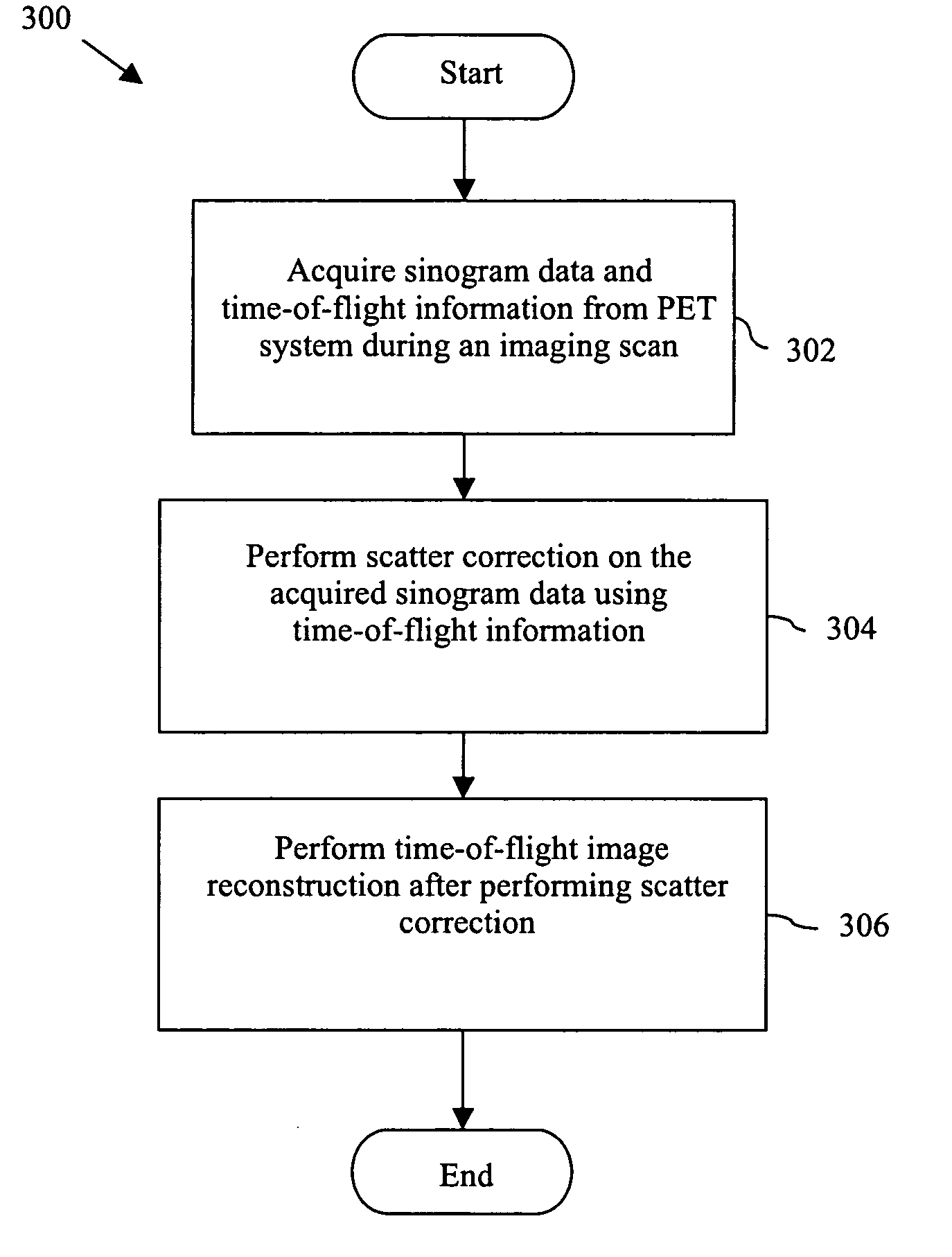
[0015] Various embodiments of the invention generally provide a method and a system for controlling a positron emission tomography (PET) system.

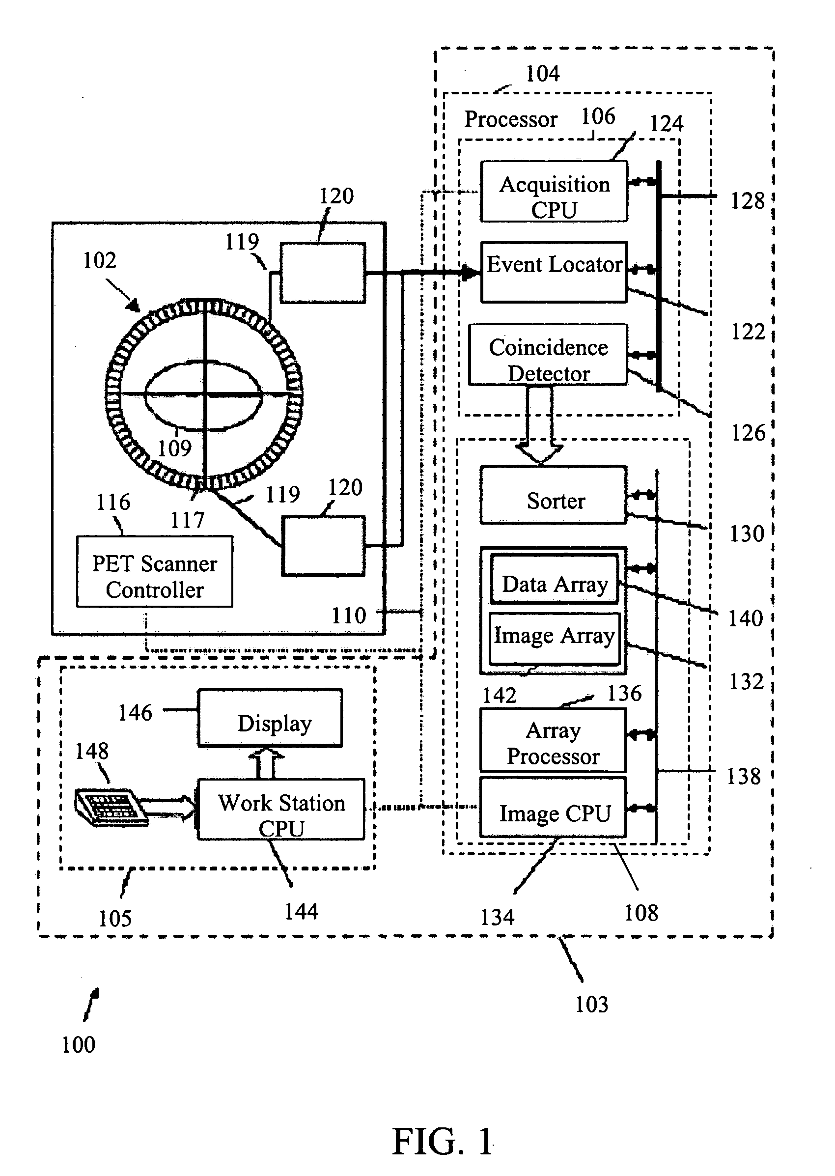
[0016]FIG. 1 is a block diagram of an exemplary embodiment of a PET system 100 in which various embodiments of the invention may be implemented. PET system 100 includes a plurality of detector ring assemblies. One such detector ring assembly, detector ring assembly 102, is illustrated in FIG. 1. PET system 100 further includes a controller 103 to control normalization and image reconstruction processes. Controller 103 includes a processor 104 and an operator workstation 105. Processor 104 includes a data acquisition processor 106 and an image reconstruction processor 108, which are interconnected via a communication link 110. PET system 100 acquires scan data and transmits the data to data acquisition processor 106. The scanning operation is controlled from operator workstation 105. The data acquired by data acquisition processor 106 is rec...


PUM


Abstract

A method and system for controlling a positron emission tomography (PET) system is disclosed. The method includes acquiring image data and time-of-flight information from a PET system during an imaging scan. Further, the method includes performing scatter correction on the image data using the time-of-flight information.

Description

BACKGROUND OF THE INVENTION [0001] This invention relates generally to positron emission tomography (PET) systems, and more particularly to performing scatter correction in time-of-flight (TOF) PET systems. [0002] A PET system typically includes a detector ring assembly having rings of detectors that encircle a patient or an object. The detectors detect photons emitted from an annihilation point in the object. Only photons that are detected by two detectors within a predefined time gap are recorded as coincident photons. The two detectors, together, are called a detector pair. When a detector pair detects coincident photons it is assumed that they arose from an annihilation point on the line between the two detectors. When a number of such events are acquired, one of a number of known reconstruction algorithms is applied to estimate the distribution of annihilations within the patient. [0003] A photon generated by an annihilation event may scatter after collision with an atom presen...

Claims


Application Information

Patent Timeline
Patent Type & Authority Applications(United States)
IPC IPC(8): G01T1/164
CPCG01T1/2985
Inventor STEARNS, CHARLES WILLIAMMANJESHWAR, RAVINDRA MOHAN
Owner GENERAL ELECTRIC CO
Why Eureka
Try Eureka