Wiper motor for driving wiper

Active Publication Date: 2006-07-27
DENSO CORP
View PDF11 Cites 16 Cited by
  • Summary
  • Abstract
  • Description
  • Claims
  • Application Information

AI Technical Summary

Benefits of technology

[0010] The present invention addresses the above disadvantages. Thus, it is an objective of the present invention to provide a wiper motor, which enable a reduction in t

Problems solved by technology

Thus, the number of components and the number of assembling steps are disadvantageously increased.
In such a case, water (e.g., rain water droplets or car wash water) may possibly intrude into an interior of the vehicle body along the output shaft, possibly causing intrusion of the water into the gear hous

Method used


Image

  • Wiper motor for driving wiper
  • Wiper motor for driving wiper
  • Wiper motor for driving wiper

Examples


Example

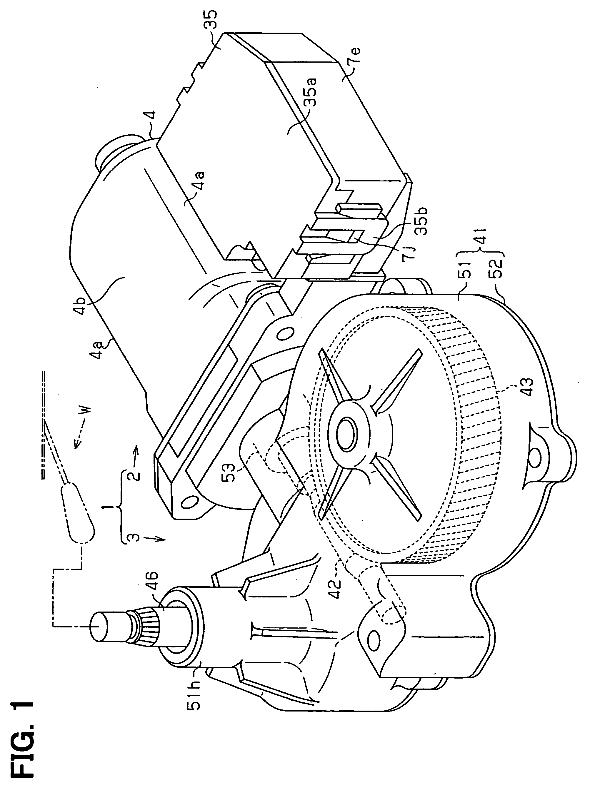
[0023] A wiper motor according to an embodiment of the present invention will be described with reference to FIGS. 1 to 9. In the present embodiment, the wiper motor is implemented as a wiper motor of a rear wiper system of a vehicle. As shown in FIG. 1, the wiper system includes the wiper motor (hereinafter, simply referred to as a motor) 1 and a wiper W. The motor 1 includes a motor main body 2 and a gear section 3.

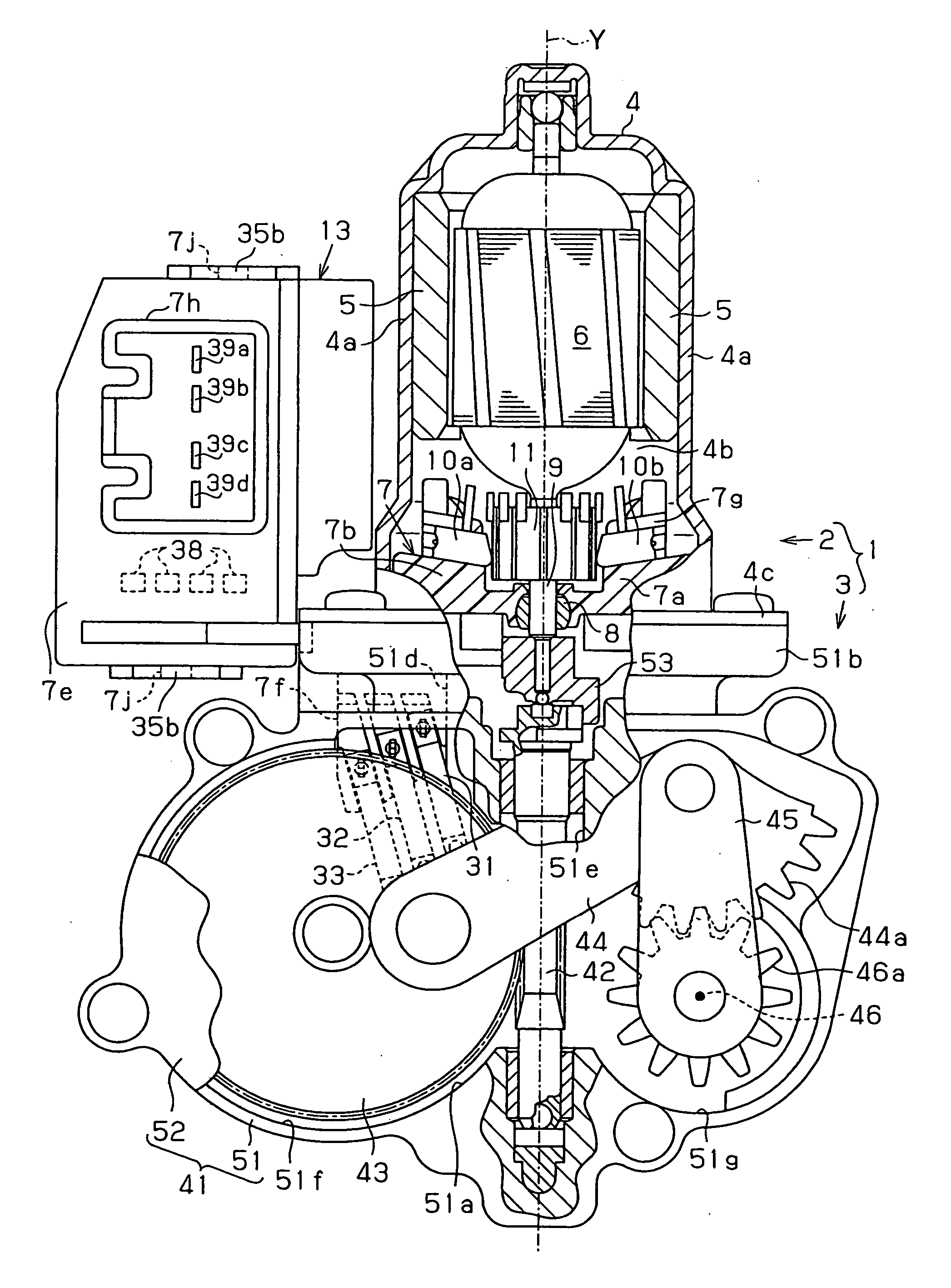
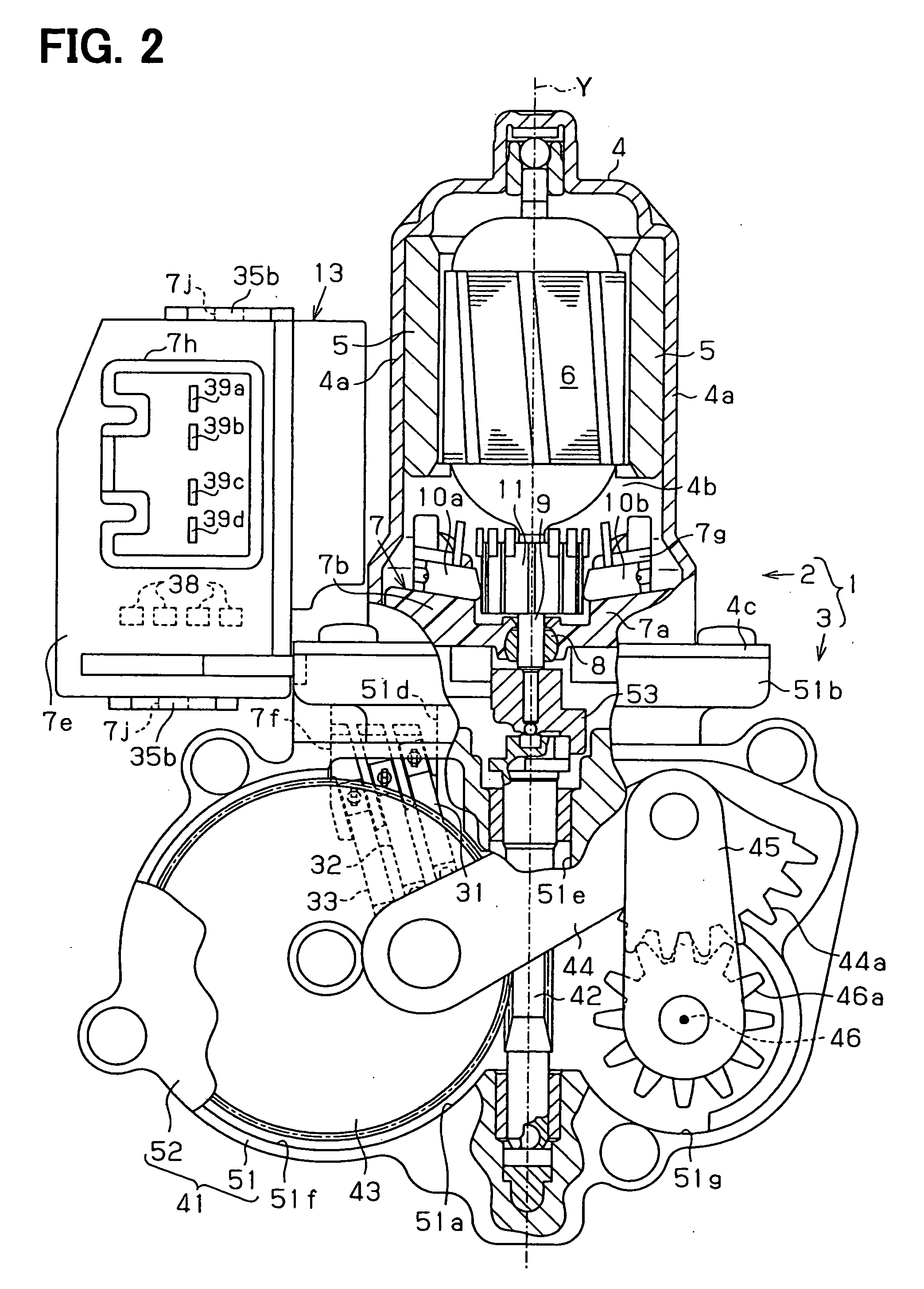
[0024] With reference to FIG. 2, the motor main body 2 includes a yoke housing (hereinafter, simply referred to as a yoke) 4, two magnets 5 and an armature 6. The yoke 4 is formed into a cup shape. The magnets 5 are fixed to an inner peripheral surface of the yoke 4. The armature 6 is rotatably supported in the yoke 4. The yoke 4 of the present embodiment includes two arcuate segments 4a (FIGS. 1 and 2) and two planar segments 4b (FIG. 1). The two arcuate segments 4a are opposed to each other in a direction perpendicular to an axis of the armature 6 (a direction perpen...


PUM


Abstract

A connector part extends outward of a yoke housing from a holder base and is connectable with an external connector to receive an electric signal. A contact base extends from the holder base into an interior of the gear housing through a communication hole, which is formed in a yoke housing side end of the gear housing. The contact base supports terminals, which provide an electrical connection between stationary contacts and brushes. An intermittent drive unit is installed to the connector part to intermittently drive an armature through the brushes based on the electric signal received from the external connector.

Description

CROSS REFERENCE TO RELATED APPLICATION [0001] This application is based on and incorporates herein by reference Japanese Patent Application No. 2005-14363 filed on Jan. 21, 2005. Furthermore, this application is copending with U.S. patent application Ser. No. 11 / 199,067 filed on Aug. 9, 2005 for “MOTOR APPARATUS HAVING ROTATIONAL POSITION DETECTOR” and assigned to a common assignee.BACKGROUND OF THE INVENTION [0002] 1. Field of the Invention [0003] The present invention relates to a wiper motor for driving a wiper. [0004] 2. Description of Related Art [0005] A wiper motor of one previously proposed wiper system installed in, for example, a vehicle includes an automatic stop switch (an automatic stop mechanism for automatically stopping a wiper at a predetermined position). In this motor, even when a wiper switch is turned off to stop the wiper (the wiper having a wiper arm and a wiper blade), the wiper is not immediately, unconditionally stopped. Rather, upon turning off of the wipe...

Claims


Application Information

Patent Timeline
IPC IPC(8): H02K11/00H02K7/10
CPCB60S1/0803B60S1/166B60S1/583H02K5/225H02K7/1166H02K11/00E05B71/00
Inventor YAGI, HIDEYUKIMURAKAMI, SEIICHITAKEUCHI, MASANORIKOBAYASHI, NAOHITO
Owner DENSO CORP
Why Eureka
Try Eureka