Optical lens providing omni-directional coverage and illumination

a technology of optical lens and illumination, applied in the field of extreme wide angle imaging, can solve the problems of high optical performance, high cost, and high cost, and achieve the effect of improving image quality

Inactive Publication Date: 2006-07-27
MISTRAL
View PDF8 Cites 38 Cited by
  • Summary
  • Abstract
  • Description
  • Claims
  • Application Information

AI Technical Summary

Benefits of technology

[0029] The wide angle imaging assembly of the invention may further comprise a mechanical connector having a first edge and a second edge. The first edge of the connector can be designed to connect to the holding element. The second edge of the connector can be designed to connect to an image capture device, such that the image capture device is positioned coaxially with the optical block, facing the blo

Problems solved by technology

The main disadvantage of these prior art methods is their relative complexity.
Some prior art methods make use of moving/rotating mechanisms, which require frequent alignment and very often turn out to be maintenance-intensive.
The main disadvantages of the methods described in U.S. Pa

Method used


Image

  • Optical lens providing omni-directional coverage and illumination
  • Optical lens providing omni-directional coverage and illumination
  • Optical lens providing omni-directional coverage and illumination

Examples


Embodiment Construction

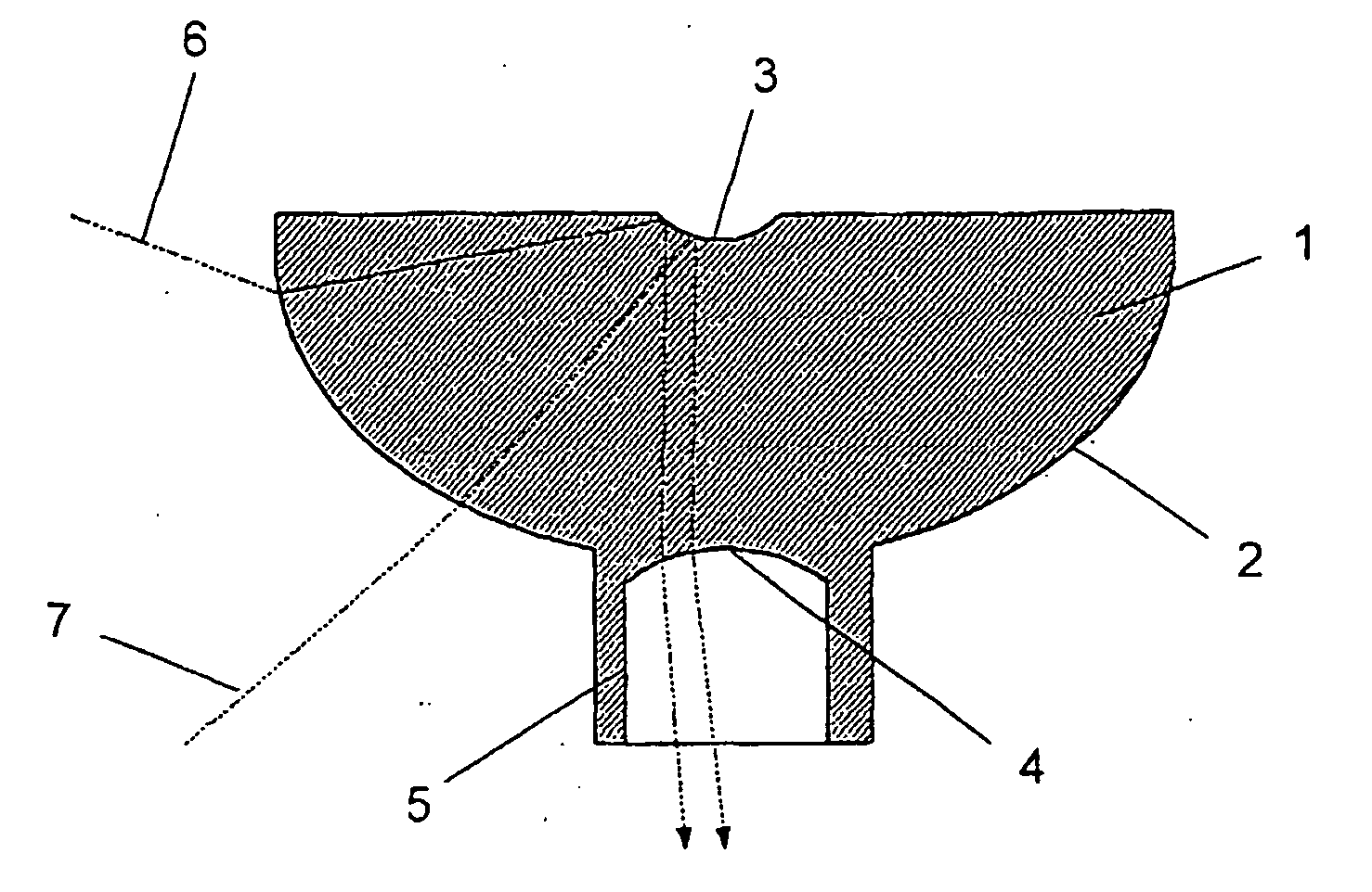
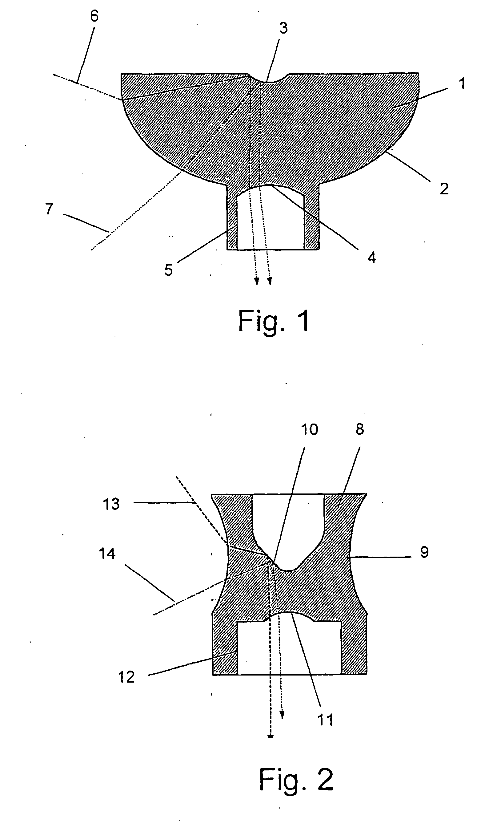
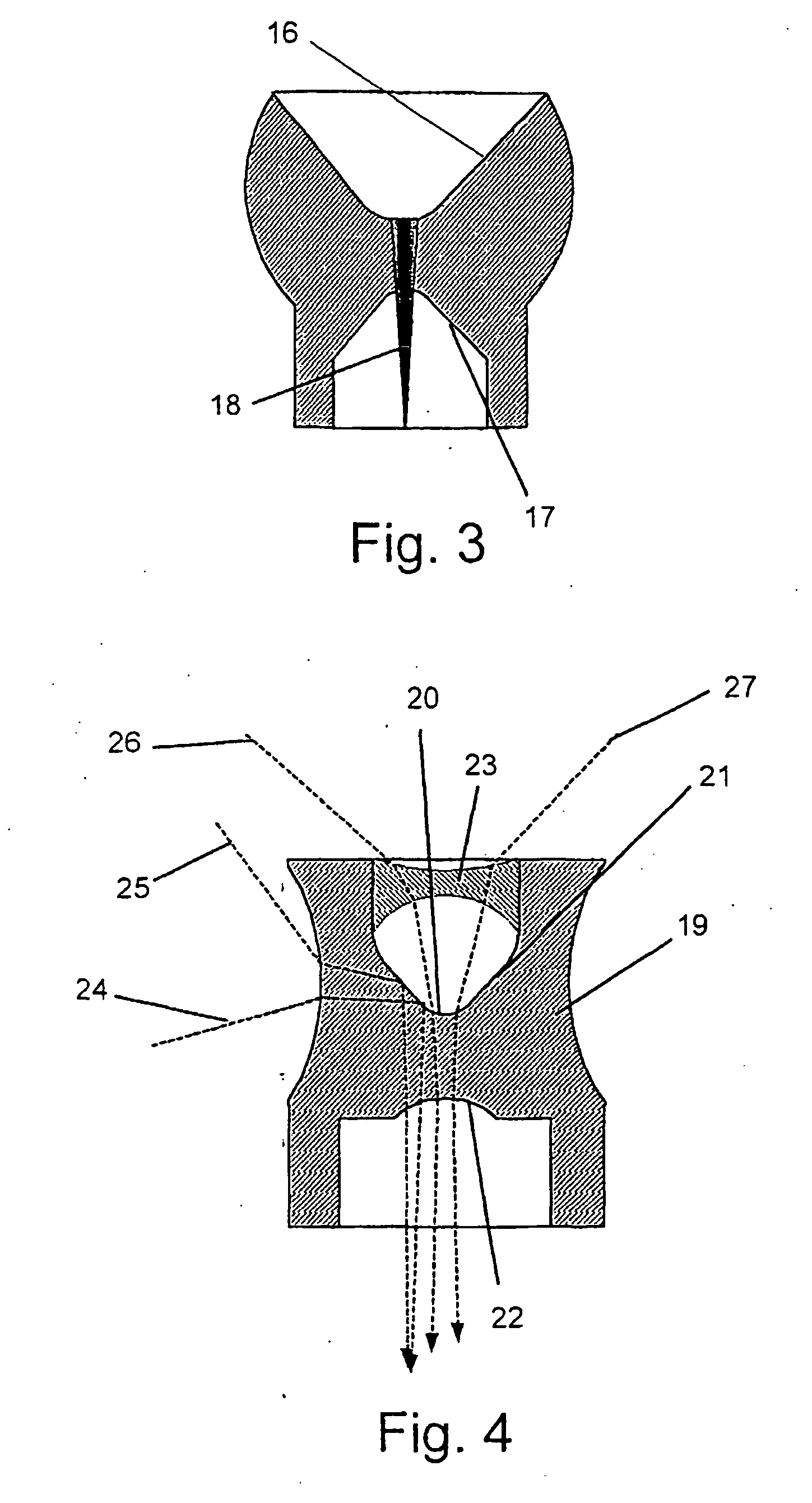
[0053] The preferred embodiments of the present invention are described hereinbelow with reference to the figures. All of the figures show a cross-sectional view of only the main optical components of an electro-optical system. The system is designed to produce an image of a cylindrical or nearly spherical field of view. The main optical components, which are shown, are generally those that are responsible for gathering the light rays from the cylindrical or nearly spherical field of view at the same instant, and directing those light rays to the other components of the system. As it is clear that several different components comprise the entire electro-optical system, reference to only the main optical components is made for the sake of brevity and since other components and their incorporation in the system are known from the prior art and are well within knowledge of those skilled in the art. The figures are schematic and designed to provide a general perception of preferred embo...


PUM


Abstract

The invention presents a wide-angle imaging assembly which comprises a main lens produced from an aspheric optical block. The aspheric optical block comprises a vertical axis of symmetry; a transparent upper surface, at least part of which is capable of reflecting rays that impinge upon it from the interior of the optical block; a transparent perimeter surface; and a transparent lower surface. The optical block is fabricated from material selected to enable optical transmittance of a specific spectral range. Light rays in the specific spectral range originating in a first scene, having a 360 degrees panoramic perimeter, are refracted by the transparent perimeter surface, enter the optical block, are then reflected by the upper surface towards the transparent lower surface, where they are then refracted by the transparent lower surface, and exit through it.

Description

FIELD OF THE INVENTION [0001] The present invention relates to the field of extremely wide-angle imaging. More specifically, it relates to optical structures that enable the coverage and / or illumination of a panoramic or nearly spherical field of view, suitable for video or still imaging. BACKGROUND OF THE INVENTION [0002] Imaging of a large field of view has many applications in the fields of defense, security, monitoring, entertainment, industry, medical imaging and many other fields. Imaging of a panoramic or nearly spherical field of view, using a single image-capturing device, is especially applicable for a variety of needs due to its relative simplicity, low-cost and miniaturization possibilities. [0003] Security cameras often require the ability to view as large a field of view as possible to enable imaging of all occurrences in a scene for purposes of real-time surveillance and warning or for documentation and restoration of images at later stages. [0004] Inner body imaging ...

Claims


Application Information

Patent Timeline
IPC IPC(8): G02B13/06
CPCA61B1/00177G02B13/06G03B37/06G03B2215/0582
Inventor GAL, EHUDGRAISMAN, GILLITEYGA, GENNADIY
Owner MISTRAL
Why Eureka
Try Eureka