
Heat radiation structure for secondary battery module, and switching board and secondary battery module having the same

Active Publication Date: 2006-07-27
LG ENERGY SOLUTION LTD
View PDF7 Cites 25 Cited by
  • Summary
  • Abstract
  • Description
  • Claims
  • Application Information

AI Technical Summary

Benefits of technology

[0009] Specifically, a primary object of the present invention is to provide a heat dissipation structure, which is connected to switching elements and the size of which can be easily increased or decreased depending upon desired electrical capacity and output.
[0039] As described above, the circuit units, which control the operation of the battery, are connected with each other in such a manner that the circuit units surround the battery module according to the present invention, and therefore, the total size of the battery module is greatly reduced.

Problems solved by technology

Furthermore, devices, which are subject to a large number of external impacts and vibrations, such as electric bicycles and electric vehicles, require stable electrical connection and physical connection between components constituting the battery module.
However, this structure of the battery module, especially, the elements for controlling overcharge, overdischarge, and overcurrent, have several problems.
The switching elements used to control overcharge generate a large amount of heat.
For this reason, the switching elements are generally mounted at the outside of the battery module while the switching elements are connected to an additional heat dissipation structure, and therefore, it is difficult to appropriately modify the heat dissipation structure when the size of the battery module is to be increased or decreased depending upon desired electrical capacity and output.
Also, the size of the heat dissipation structure is an obstacle to design of a compact battery module.

Method used


Image

  • Heat radiation structure for secondary battery module, and switching board and secondary battery module having the same
  • Heat radiation structure for secondary battery module, and switching board and secondary battery module having the same
  • Heat radiation structure for secondary battery module, and switching board and secondary battery module having the same

Examples


Embodiment Construction

[0050] Now, preferred embodiments of the present invention will be described in detail with reference to the accompanying drawings. It should be noted, however, that the scope of the present invention is not limited by the illustrated embodiments.

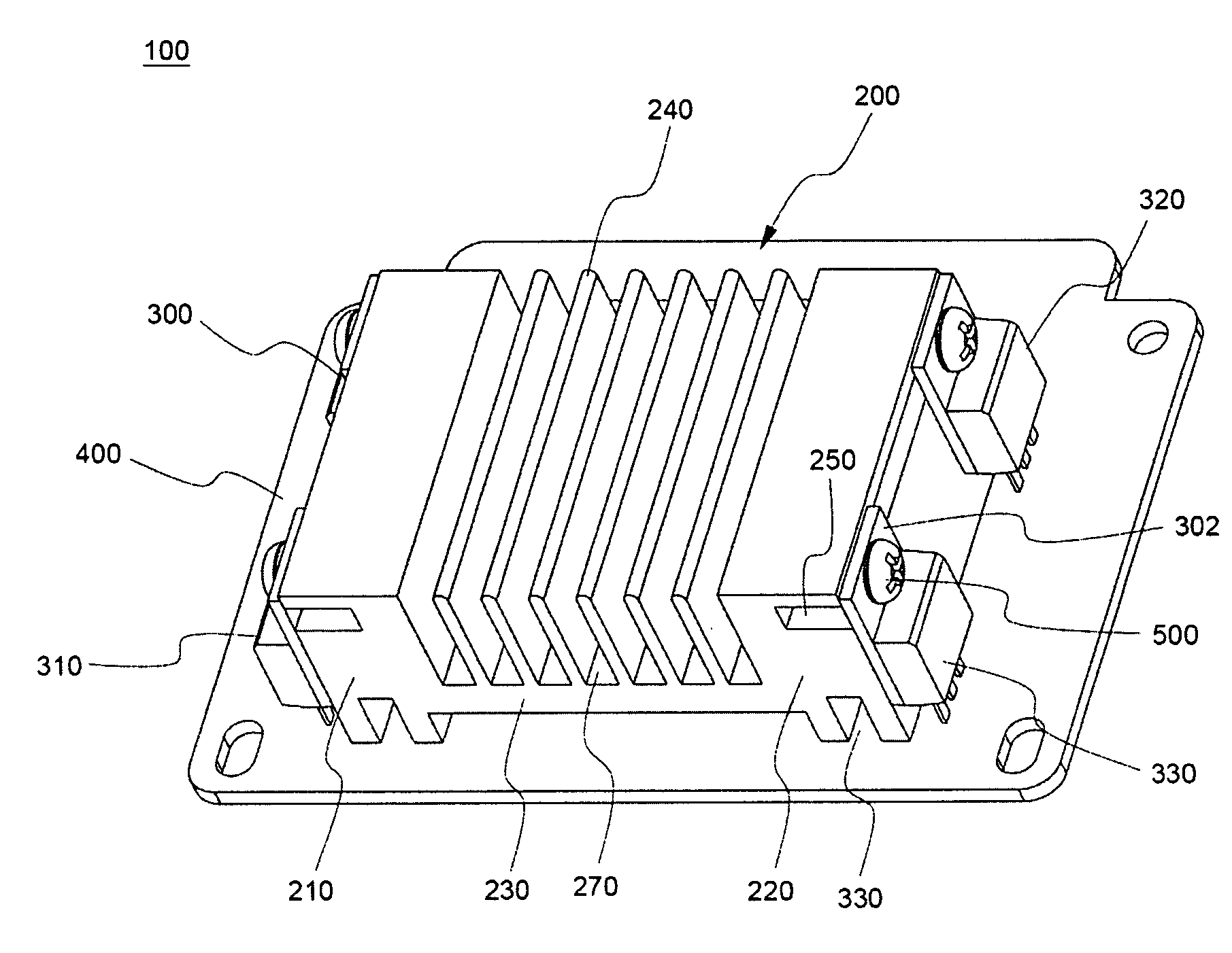
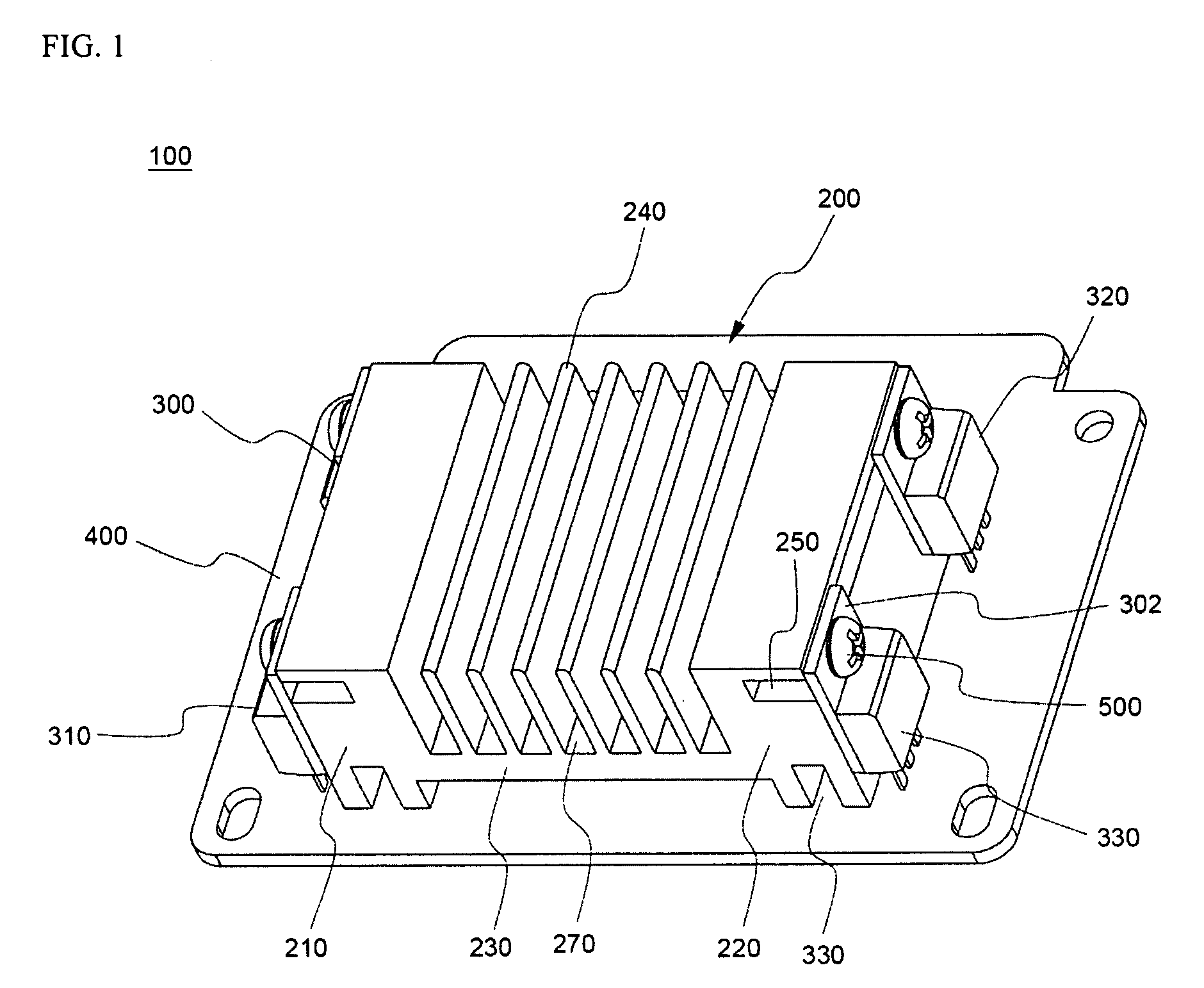
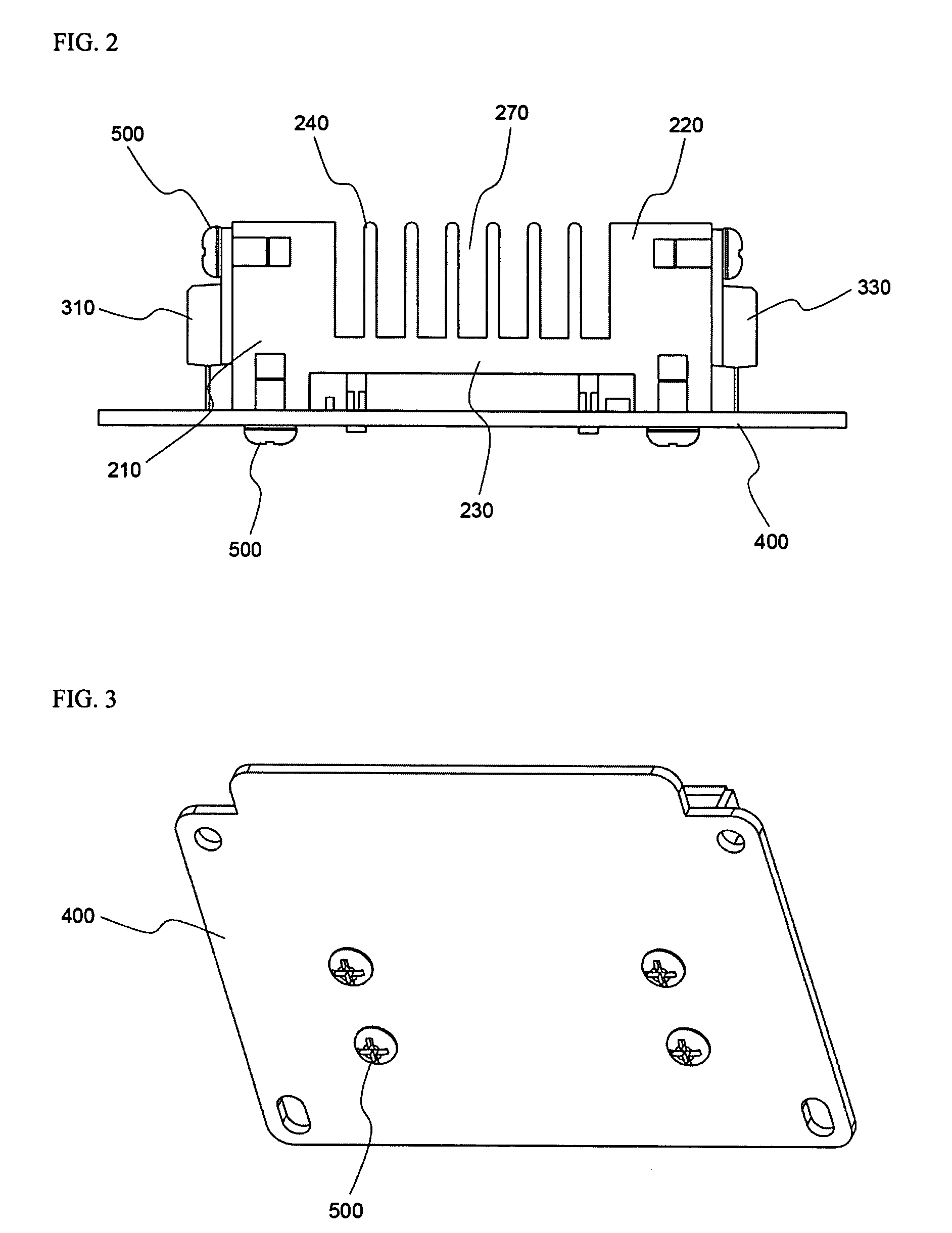
[0051] FIGS. 1 to 3 typically illustrate a switching board 100 having a heat dissipation structure according to a preferred embodiment of the present invention, in a perspective view, a vertical sectional view, and a bottom view, respectively.

[0052] Referring to FIGS. 1 to 3, the switching board 100 includes a rectangular heat dissipation structure 200 mounted on a printed circuit board (PCB) 400 while the heat dissipation structure 200 is connected to four field effect transistor (FET) elements 300, 310, 320, and 330, which are switching elements.

[0053] The heat dissipation structure 200 is constructed such that the FET elements 300, 310, 320, and 330 are coupled to the opposite side frames 210 and 220, and a plurality of heat dissipati...


PUM


Abstract

Disclosed herein is a heat dissipation structure that is capable of effectively dissipating heat generated from switching elements for controlling overcharge, overdischarge, and overcurrent of a high-output, large-capacity secondary battery module or pack having a plurality of unit cells electrically connected with each other such that the unit cells can be charged and discharged. A switching board has the heat dissipation structure and the switching elements, which are mounted on a printed circuit board. A secondary battery module includes the switching board. The size of the heat dissipation structure according to the present invention can be effectively increased or decreased depending upon desired electrical capacity and output. Also, the heat dissipation structure provides high heat dissipation efficiency even though the heat dissipation structure is compact.

Description

FIELD OF THE INVENTION [0001] The present invention relates to a heat dissipation structure for secondary battery modules or packs and a switching board and a secondary battery module having the same, and, more particularly, to a heat dissipation structure that is capable of effectively dissipating heat generated from switching elements for controlling overcharge, overdischarge, and overcurrent of a high-output, large-capacity secondary battery module or pack having a plurality of unit cells electrically connected with each other such that the unit cells can be charged and discharged, a switching board having the heat dissipation structure and the switching elements, which are mounted on a printed circuit board, and a secondary battery module including the switching board. BACKGROUND OF THE INVENTION [0002] Recently, a secondary battery, which can be charged and discharged, has been widely used as an energy source for wireless mobile devices. Also, the secondary battery has attracte...

Claims


Application Information

Patent Timeline
IPC IPC(8): H05K7/20H01M50/211H01M50/569
CPCH01M2/1061H01M6/42H01M10/425H01M10/482H01M10/486H01M10/5004H01L2924/0002H01M10/5016H01M10/5046H01L2924/00H01M10/625H01M10/6551H01M10/613Y02E60/10H01M50/569H01M50/211
Inventor HA, JIN WOONGKIM, JEEHOLEE, HANHO
Owner LG ENERGY SOLUTION LTD
Learn More