Dynamic correction of sensed temperature

a technology of dynamic correction and temperature, applied in the field of display temperature correction, can solve the problems of inability to accurately reflect the ambient temperature, inability to adjust the comfort of individuals within the environment associated with the hvac system, and inability to adjust the temperature response.

Active Publication Date: 2006-07-27
CARRIER CORP
View PDF12 Cites 37 Cited by
  • Summary
  • Abstract
  • Description
  • Claims
  • Application Information

AI Technical Summary

Benefits of technology

[0005] In one aspect of the invention, a method is provided for correcting a temperature signal from a temperature sensor for sensing an ambient temperature in an environment wherein the sensor may be affected by a local heating/cooling source. The method includes determining whether the local heating/cooling source is in an on or an off state, monitoring the length of time, either continuously or at selected time intervals, the local heating/cooling source has been in its current on/off state, estimating a temperature correction factor based upon the current on/off state of t...

Problems solved by technology

Therefore, if the temperature signal received by the HVAC controller does not represent the true temperature of the environment with which the HVAC system is associated, but rather represents an incorrect temperature due to the effects of heat from the LCD bac...

Method used


Image

  • Dynamic correction of sensed temperature
  • Dynamic correction of sensed temperature

Examples


Embodiment Construction

[0015] The invention will be described herein with reference to a temperature sensing and display device, commonly known as a thermostat, as applied to a heating, ventilating and air conditioning system. It is to be understood, however, that the basic concept of the present invention may be applied for the correction of any sensed temperature that has been corrupted by the presence of a local heat source or cooling source.

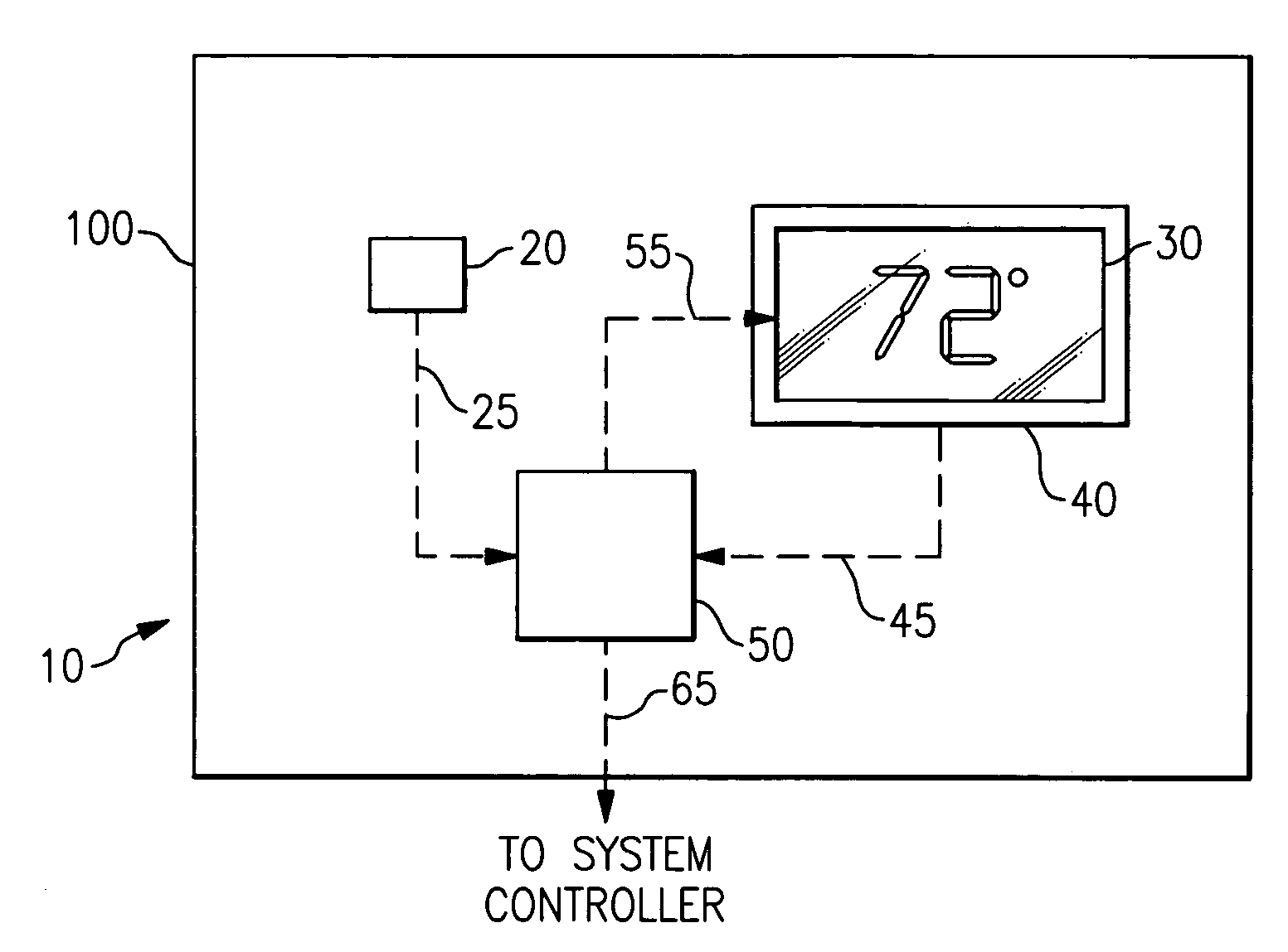
[0016] Referring now to FIG. 1, the thermostat 10 includes a temperature sensor 20, a temperature display device 30, a liquid crystal display (LCD) backlight 40 and a controller 50, all housed in a common enclosure 100. The temperature display device 30 functions in a conventional manner to display a temperature corresponding to a temperature signal 55 received from the controller 50. The LCD backlight 40 is provided in operative association with the temperature display device 30 to backlight the display device 30, thereby improving the illumination of the display...


PUM


Abstract

A thermostat (10) for sensing the ambient temperature in an environment includes an enclosure (100) housing a temperature sensor (20) for sensing the temperature within the enclosure, a temperature display device (30), a liquid crystal display (LCD) backlight (40) operative in its on state to illuminate the temperature display. A controller (50) operatively associated with the thermostat monitors the current on/off state of the backlight and the length of time the backlight has been in its current state, estimates a temperature correction factor using a simplified Discrete Kalman Filter estimator, and applies the temperature correction factor to correct the sensed temperature for the heat generated by the backlight (40).

Description

CROSS-REFERENCE TO RELATED APPLICATION [0001] This application claims priority to and the benefit of U.S. Provisional Patent Application Ser. No. 60 / 647,095, filed Jan. 26, 2005, and entitled DYNAMIC CORRECTION OF SENSED TEMPERATURE, which application is incorporated herein by this reference.BACKGROUND OF THE INVENTION [0002] The present invention relates generally to the correction of the temperature displayed by a device and, more particularly, to the correction of the displayed temperature due to the effects of heat generated by a liquid crystal display (LCD) backlighting the display. [0003] In certain applications, including in commercial heating, ventilating and air conditioning (HVAC) systems, temperature display devices, such as for example thermostats, are employed that display the sensed temperature on a display screen. Often, the display screens are backlighted with an LCD to improve illumination. Typically, the temperature sensor is housed in the same enclosure with the d...

Claims


Application Information

Patent Timeline
IPC IPC(8): G01K15/00
CPCG01K1/20
Inventor KOLK, RICHARD A.
Owner CARRIER CORP
Why Eureka
Try Eureka