Zip lock

a technology of zippers and seals, applied in the field of sealing devices, can solve the problems of poor quality sealing of the container on which the plastic zipper is mounted, prone to air leakage, and continuous gap, and achieve the effect of reducing the chance of air leakage and enhancing the tightness

Inactive Publication Date: 2006-07-27
INTELLI INNOVATIONS +1
View PDF7 Cites 48 Cited by
  • Summary
  • Abstract
  • Description
  • Claims
  • Application Information

AI Technical Summary

Benefits of technology

[0010] A main object of the present invention is to provide a zip lock which is capable of sealing a plastic bag with enhanced tightness and less chance of air leakage with a view to significantly overcome the problems of the relevant conventional arts.
[0011] Another object of the present invention is to provide a zip lock which is expected to be stronger in resisting tearing stress, and to have a longer expected life span under ordinary course of applications.
[0012] Another object of the present invention is to provide a zip lock comprising a zip fastener and a lock fastener which are arranged to engage with each other, wherein the points of engagement between the zip fastener and the lock fastener are substantially rounded so as to avoid stress concentration, to facilitate more accurate engagement between the zip fastener and the lock fastener, and to facilitate simpler manufacturing steps of the zip lock.
[0013] Another object of the present invention is to provide a zip lock which is easy to use for sealing the plastic bag and convenient to be unsealed, so as to facilitate widespread application of the present invention.

Problems solved by technology

First, it is readily deduced from the drawings and the claims of that patent that the male hook and the female hook, when sealed and interlocked with each other, leave a continuous gap between the relevant male hook and the female hook.
As such, the interlocking between the male hook and the female hook is liable to be insecure, especially when significant tolerance during the manufacturing process is present.
Otherwise, any failure for fit engagement between the male hook and the female hook, possibly due to manufacturing defect (e.g. too big or too small of the male hook), will cause the engagement between the male and the female hook to be too loose and result in poor quality sealing of the container on which the plastic zipper is mounted.
From this analysis, the above-mentioned patent invention is unsatisfactory both fro the point of view of manufacturing process which highly likely leads to unsatisfactory performance of the ultimate plastic zipper.
It is submitted, although this synthetic resin fastener is capable of accomplishing fairly sealing, it nevertheless possesses certain discrepancies which make the synthetic resin fastener less than satisfactory.
First of all, the disclosed design in the patent specification involves very sharp ‘ridges’ and ‘projections’ constituting very sharp corners at the male and female talon and this geometrical feature brings difficulties in both the manufacturing process and the ultimate utilization of the fastener.
From the manufacturing perspective, those very sharp edges or corners are difficult to manufacture and, if one employed extrusion technique, it would be very difficult to predict and control the quality of the final product because the sharp corners are liable to deform during the relevant manufacturing process.
As a result, the engagement between the male and female talon may not be satisfactorily fit so as to allow air or liquid leakage via the fastener.
On the other hands, from the application perspective, the sharp edges and corners reduce the product life span of the fastener because, as a matter of simple materials mechanics, the shape edge and corners concentrate any stress applied to the fasteners and therefore, the fastener may break at the sharp edges or corners very easily.

Method used


Image

  • Zip lock
  • Zip lock
  • Zip lock

Examples


Embodiment Construction

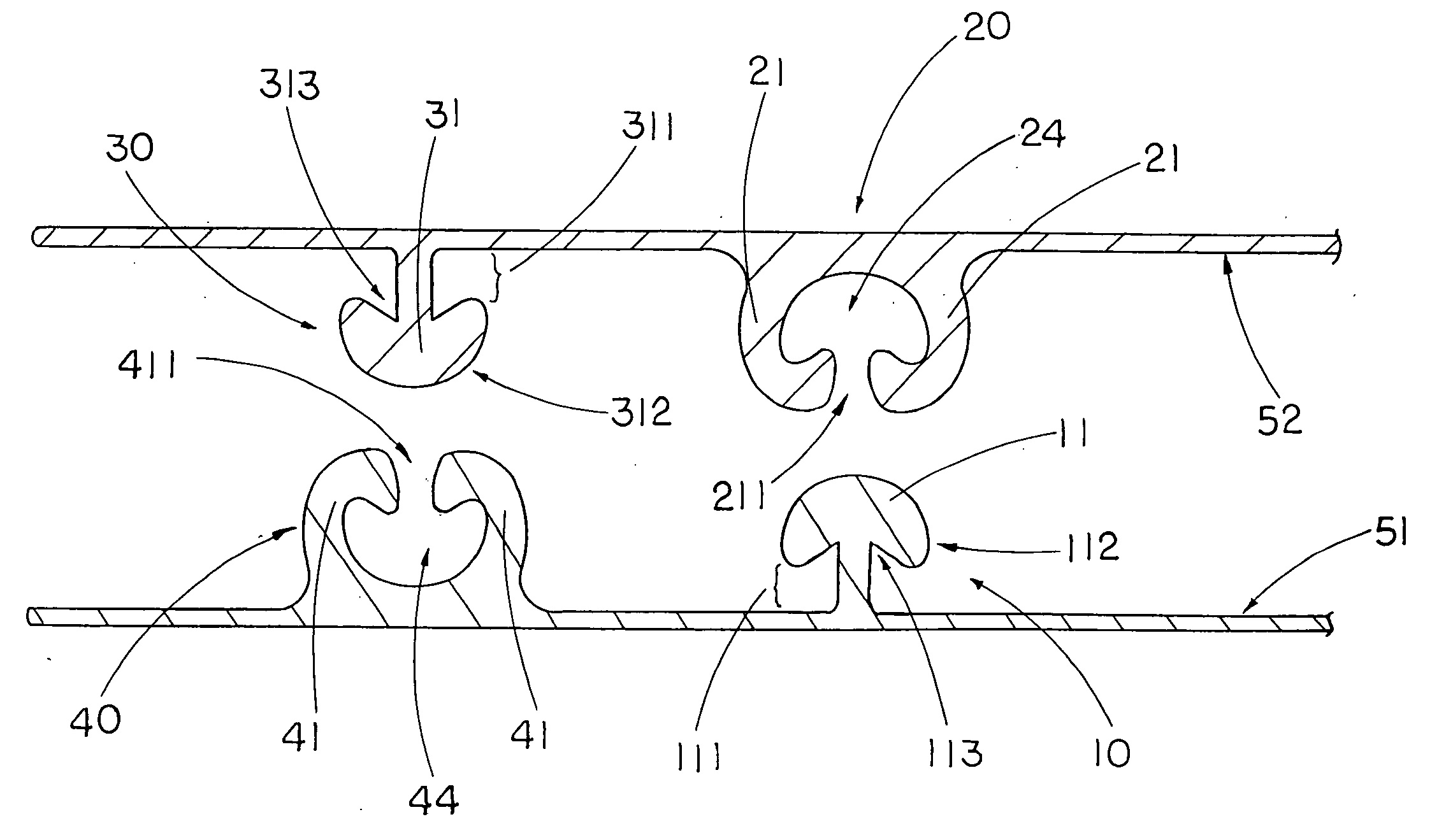
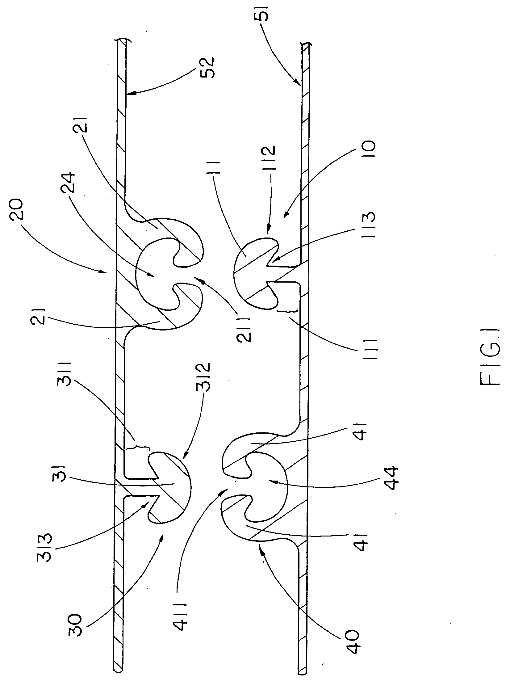
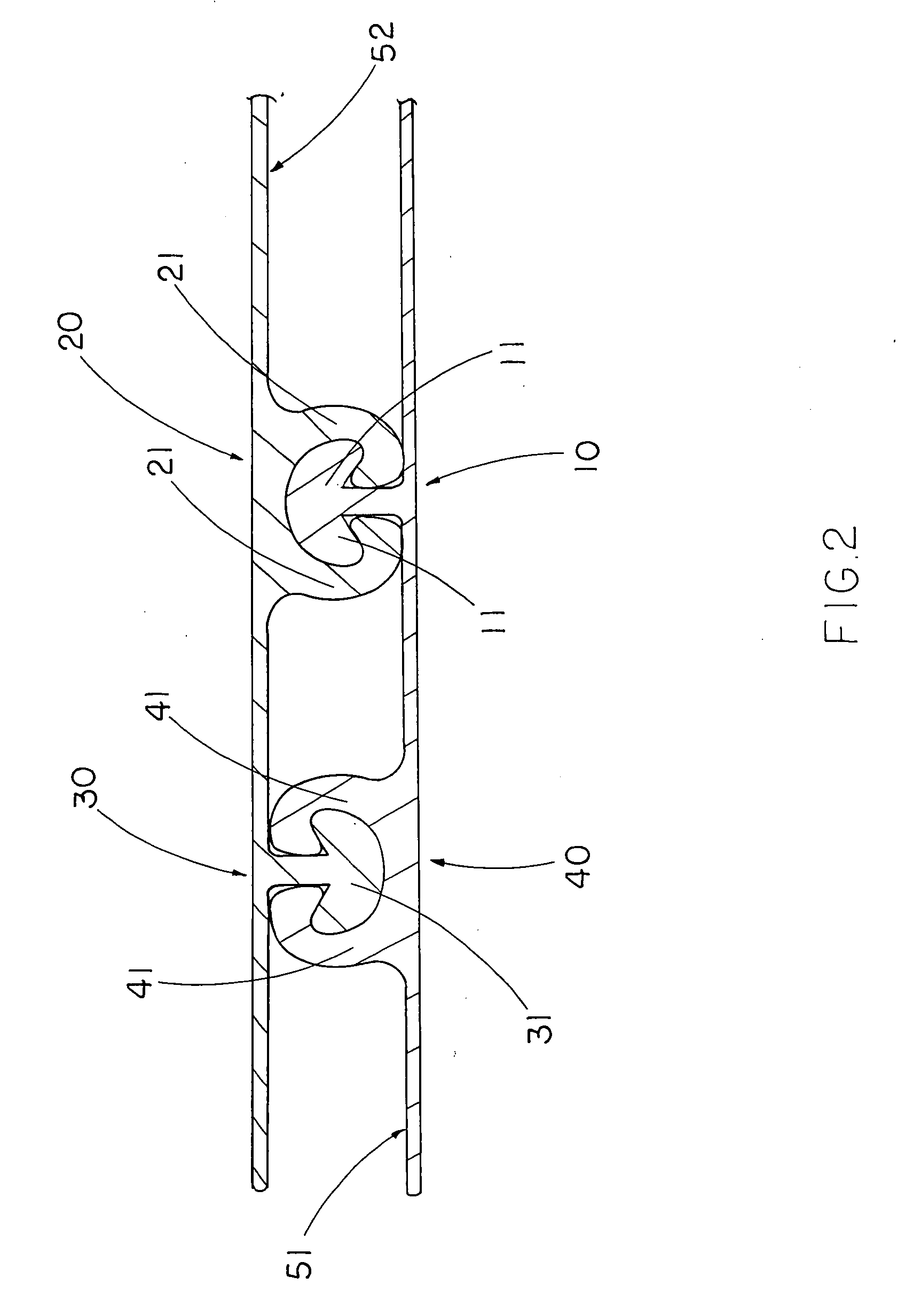
[0024] Referring to FIG. 1 and FIG. 2 of the drawings, a zip lock for a storage bag having a first surface 51 and a second surface 52 according to a preferred embodiment of the present invention is illustrated, in which the zip lock comprises a zip fastener 10 and a lock fastener 20 integrally provided on the first surface 51 and the second surface 52 respectively.

[0025] The zip fastener 10 has a zip body 11 which is integrally extended from the first surface 51, and has a neck portion 111 extended from the first surface 51, and at least an enlarged head portion 112 integrally extended from the neck portion 111 to form two round zipping grooves 113 between the neck portion 111 and the head portion 112 at two sides thereof respectively.

[0026] The lock fastener 10, which is detachably attached to the zip fastener 20, has two locking arms 21 spacedly and integrally extended from the second surface 52 to define an engaging cavity 24 between the two locking arms 21, wherein each of the...


PUM


Abstract

A zip lock for a storage bag having a first surface and a second surface, includes a zip fastener and a lock fastener integrally provided on the first and second surfaces respectively. The zip fastener has two zip bodies spacedly and integrally extended from the first surface and a coupling groove extending towards the first surface at a position between two inner walls of the zip bodies. The lock fastener has two locking arms spacedly and integrally extended from the second surface and a sealing arm integrally extended from the second surface at a position between the two locking arms to form two sealing cavities, wherein the sealing arm is sealedly inserted into the coupling groove until the round end of the sealing arm is positioned at the round end of the coupling groove.

Description

BACKGROUND OF THE PRESENT INVENTION [0001] 1. Field of Invention [0002] The present invention relates to a sealing device, and more particularly to a zip lock which is capable of sealing a plastic bag with enhanced tightness and less chance of air leakage. [0003] 2. Description of Related Arts [0004] Zip locks have widely been utilized around the world to temporarily seal, for example, plastic bags. It brings the convenience which allows people to store food in the plastic bag for a prolonged period of time in a secured manner. [0005] U.S. Pat. No. 5,689,866 of Juichi Kasai et al. discloses a plastic zipper comprising a pair of female hooks and a pair of male hooks formed on the surface of respective plastic films. There are several disadvantages regarding this invention. First, it is readily deduced from the drawings and the claims of that patent that the male hook and the female hook, when sealed and interlocked with each other, leave a continuous gap between the relevant male hoo...

Claims


Application Information

Patent Timeline
Patent Type & Authority Applications(United States)
IPC IPC(8): B65D33/16A44B19/00
CPCA44B19/16Y10T24/45168B65D33/2541B65D33/2508
Inventor CHEUNG, GEORGE F.
Owner INTELLI INNOVATIONS
Why Eureka
Try Eureka