Photosensitive drum

a technology of photosensitive drums and drum bodies, applied in the field of photosensitive drums, can solve the problems of disturbance of formed images, inability to meet the contact force in the peripheral direction of the drum, and inability to form images, so as to reduce the number of drum members used to form the drum, restrict the manufacture cost, and facilitate the effect of ensuring a greater amount of elastic deformation

Inactive Publication Date: 2006-07-27
KYOCERA DOCUMENT SOLUTIONS INC
View PDF1 Cites 10 Cited by
  • Summary
  • Abstract
  • Description
  • Claims
  • Application Information

AI Technical Summary

Benefits of technology

[0022] As each flange defines a slit extending in the form of an angular hook shape surrounding an outer periphery of said fixing arm, thereby forming the fixing arm in the form of a cantilever formed integral with the flange, the number of members used to form the drum can be reduced advantageously, thus further restricting the manufacture cost.
[0023] Moreover, since opposed ends of the hook-shaped slit extend beyond a fixing element attaching portion of the fixing arm toward a base end of the fixing arm, it is easier to secure a greater amount of elastic deformation for the fixing arm, so that a desired amount of contact force can be easily set.

Problems solved by technology

Furthermore, non-uniformity in the contact force in the peripheral direction of the drum will tend to invite a twisting distortion in the drum body.
All of these conditions tend to lead to disturbance in the formed image.
Hence, in order to elastically contact the outer periphery of each flange 12 against the end face of the drum body 11 so as to realize such substantially uniform distribution of appropriate contact force along the peripheral direction of the drum, precision management of the threading depth of the screw 35 is needed and such precision management requires skill and good experience for the assembling factory worker and this also intends to invite disadvantageous increase in the manufacture cost of the drum.

Method used


Image

  • Photosensitive drum
  • Photosensitive drum
  • Photosensitive drum

Examples


second embodiment

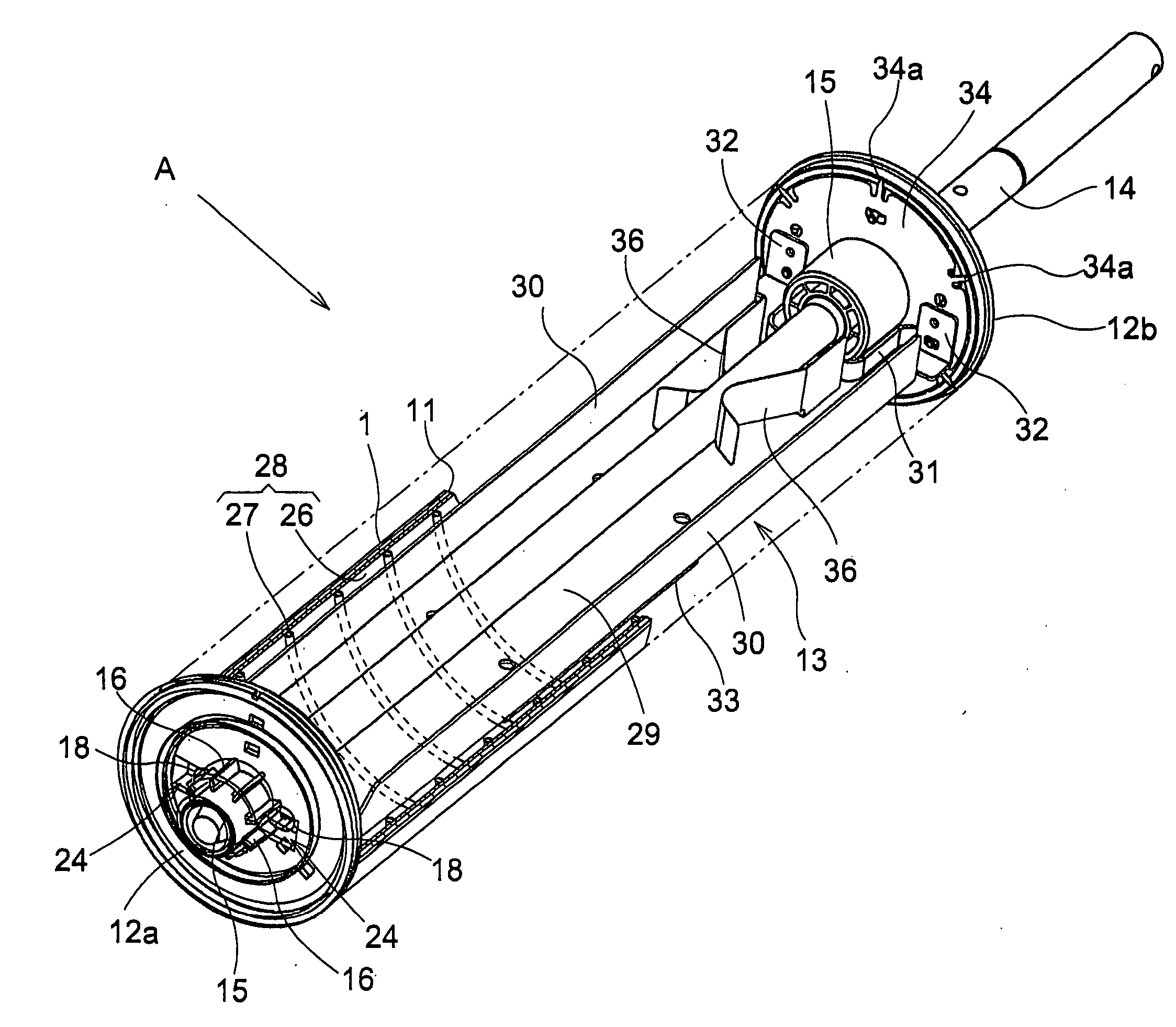
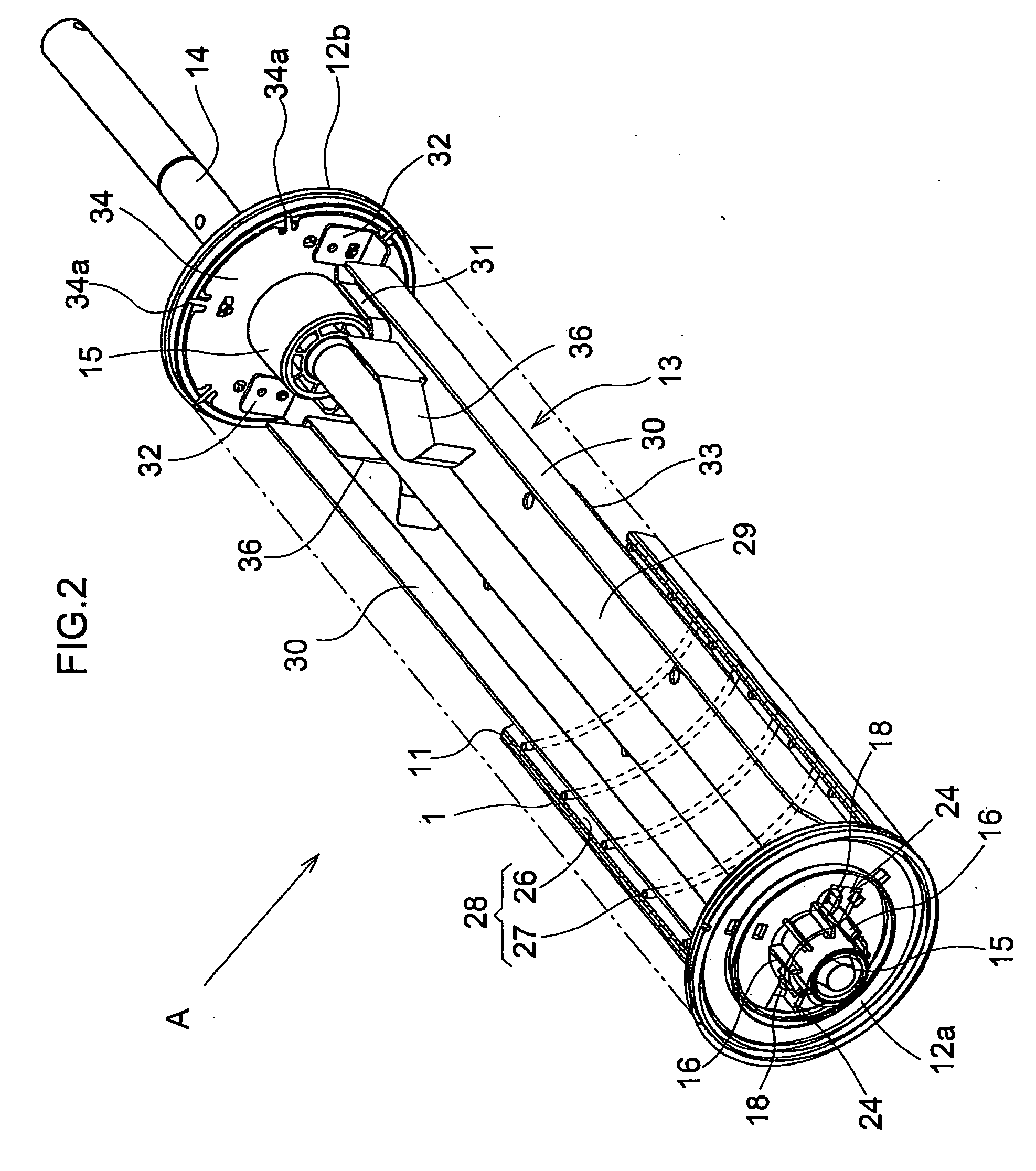
[0049]FIGS. 7 and 8 show a photosensitive drum A according to a further embodiment of the invention. In this embodiment, instead of the pair of respective flanges 12a, 12b disclosed in the first embodiment, a pair of substantially angular hooked-shaped slits 37 are defined in each flange 12a, 12b, and outer peripheries of a pair of fixing arms 18 supported like cantilevers are surrounded by the slits 37. By using these flanges 12a, 12b, the outer peripheries thereof are elastically contacted against the end face of the drum body 11.

[0050] Incidentally, although FIG. 8 illustrates the fixing construction of the front-end flange 12a to the reinforcing stay 13 as an example, the fixing construction of the rear-end flange 12b is substantially the same.

[0051] The rest of the construction is substantially the same as the first embodiment.

Other Embodiment

[0052] 1. In the photosensitive drum relating to the present invention, a fixing arm provided separately from a flange can be fixed i...


PUM


Abstract

To realize easier assembly of the photosensitive drum with appropriate contact force to the end face of the drum body, while restricting manufacture cost increase and avoiding need for high skill and/or experience for the factory worker who assembles the drum. A photosensitive drum for use in an electrophotographic image forming apparatus. The drum includes a cylindrical drum body 11 having a photosensitive layer, a pair of flanges 12a, 12b attached to opposed end faces of the drum body, a reinforcing stay 13 provided inside the drum body, a drum shaft 14 for rotatably supporting the drum body via the flanges. The flanges are fixed to the reinforcing stay in such a manner that outer peripheries of the flanges are elastically contacted against the end faces of the drum body. Each flange includes, as a cantilever-like extension thereof, a fixing arm 18 for the reinforcing stay, a leading end of the fixing arm being fixed to the reinforcing stay with the fixing arm being elastically deformed toward the inside of the drum body, such that the fixing arm provides an elastic resilience for causing the outer periphery of the flange to be elastically contacted against the corresponding end face of the drum body.

Description

BACKGROUND OF THE INVENTION [0001] 1. Field of the Invention [0002] The present invention relates to a photosensitive drum for use in an electrophotographic image forming apparatus. The drum includes a cylindrical drum body having a photosensitive layer, a pair of flanges attached to opposed end faces of the drum body, a reinforcing stay provided inside the drum body and a drum shaft for rotatably supporting the drum body via the flange. The flanges are fixed to the reinforcing stay in such a manner that outer peripheries of the flanges are elastically contacted against the end faces of the drum body [0003] 2. Related Art [0004] With the photosensitive drum of the above-noted type, when the pair of flanges are attached to the opposed end faces of the drum body, in order to restrict deformation in the drum body when the flanges are attached thereto and relative displacement between the axis of the drum body and the axis of the drum shaft, due to e.g. tolerances in the manufactures of...

Claims


Application Information

Patent Timeline
Patent Type & Authority Applications(United States)
IPC IPC(8): G03G15/00
CPCG03G15/751
Inventor NISHIMURA, RYOJI
Owner KYOCERA DOCUMENT SOLUTIONS INC
Why Eureka
Try Eureka