
Electronic coagulation scalpel

a scalpel and electric technology, applied in the field of electronic scalpels, can solve the problems of dangerous voltage values of electric scalpels, destruction of blood vessel tissues, and destruction of dead zones of vessels

Active Publication Date: 2006-07-27
TELEA MEDICAL GRP SRL
View PDF9 Cites 14 Cited by
  • Summary
  • Abstract
  • Description
  • Claims
  • Application Information

AI Technical Summary

Benefits of technology

[0016] The object of the invention is to propose a method of regulating an electronic device transmitting the wave form to the manipulator of an electronic scalpel, as well as to carry out said electronic scalpel in such a way to transfer to the tissue area to be coagulated an energy substantially equal to the energy required to obtain a proteinic denaturation transforming the fibrinogen contained in plasma into fibrin without collapse of the blood vessel.
[0019] Another object of the invention indeed is to limit as much as possible or even totally prevent collapse of the blood vessels and therefore their destruction because the area no longer supplied with blood naturally dies.
[0020] A further objects is to provide an electronic scalpel using relatively low voltages for the coagulation so that the sometimes occurred possibility of intestine perforation is removed even when operating far from it.
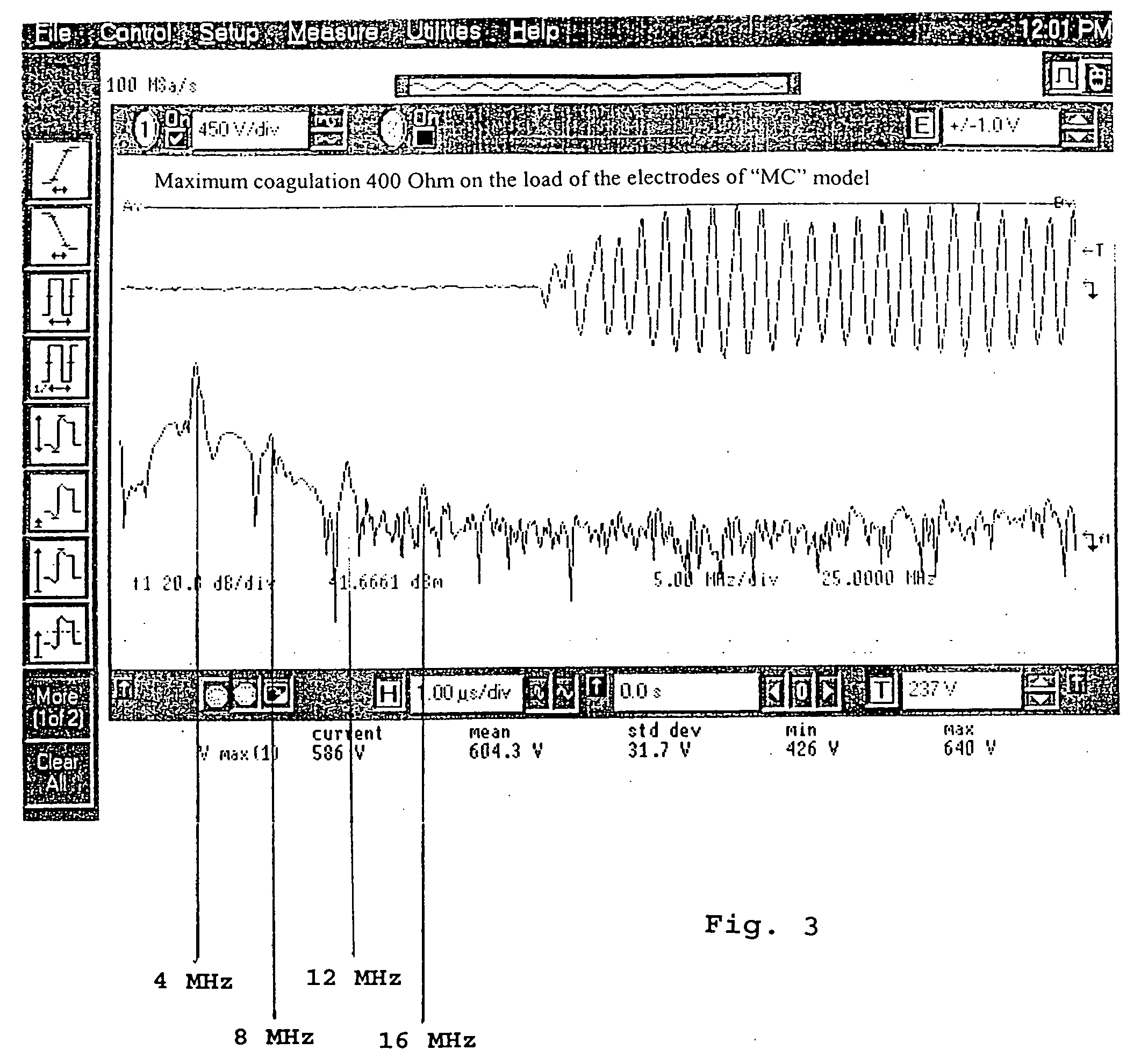
[0030] This is particularly important because at each molecule of the cellular tissue to be coagulated of different nature corresponds an ideal energy to be transmitted to reach in the present case, the correct temperature allowing transformation of the fibrinogen into fibrin without causing damages to the other adjacent cells.
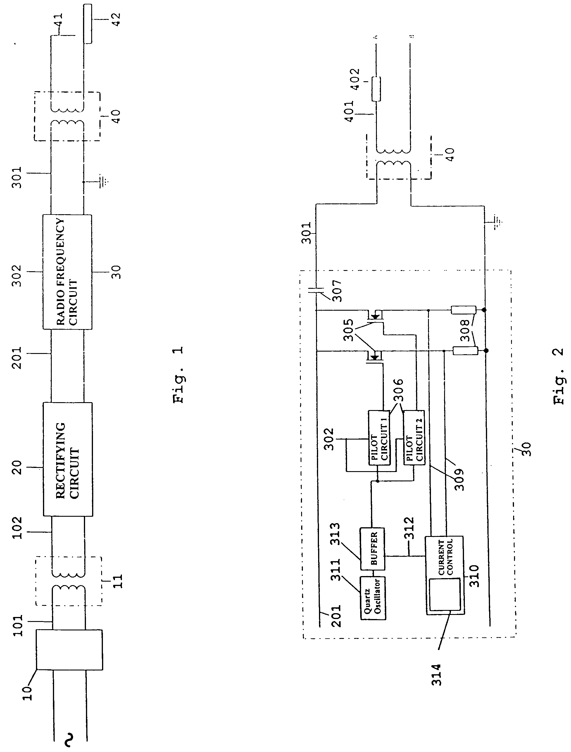
[0031] According to an embodiment of the invention, the resulting modulated wave is obtained by enabling and disabling at intermittent intervals a BUFFER circuit allowing or preventing the crystal oscillator or an eventual frequency synthesizer to transmit its pulsation to the pilot circuit of the electronic switch.

Problems solved by technology

The presently available coagulation techniques carried out with electric scalpels cause a destruction of vessels creating a dead zone and moreover the electric scalpels operate with voltage values at dangerous levels sometimes of thousands of Volts.
The danger of high voltages together with the energy excess transmitted through the electric scalpels, causes destruction of the tissues of blood vessels as above mentioned.

Method used


Image

  • Electronic coagulation scalpel
  • Electronic coagulation scalpel
  • Electronic coagulation scalpel

Examples


Embodiment Construction

[0039] According to an executive embodiment of the invention, instead of the transformer 11 and the rectifying circuit with filter 20 a stabilized switching AC / DC converter can be used, or a transformer coupled with a rectifying circuit with filter having a stabilized switching DC / DC converter in output.

[0040] In any case, the voltage 201 outgoing from these rectifying circuits should be direct and stabilized, with a prefixed value preferably comprised for instance between 50 V and 200 V, where the chosen voltage value depends on the utilization of the operating equipment.

[0041] Alternatively, for the same intended use of the equipment, the voltage can be different for different functions.

[0042] For instance, the feeding voltage can come from two feeders with two different voltage values depending on the bipolar function and the single-polar function of said scalpel, present on the same equipment.

[0043] This radio frequency circuit is better shown in FIG. 2.

[0044] The circuit i...


PUM


Abstract

The invention relates to a method of regulating the power available at the manipulator of an electronic scalpel so as to make said manipulator adapted to be used to obtain blood clotting, said electronic scalpel being of the kind comprising: at least a mains voltage rectifying circuit supplying rectified and direct voltage to at least a radio frequency circuit adapted to emit as output a current carrier signal at a main frequency set by an oscillator, said current signal feeding said manipulator through a radio frequency transformer, wherein said method consists in applying to the manipulator a wave form resulting from the sum of the carrier wave and a modulating wave of such frequency that the energy transmitted to the tissue to be coagulated is such to raise the temperature of the tissue to be coagulated until denaturation of the fibrinogen contained therein is caused and transforming it into fibrin. The invention relates also to the electronic scalpel carrying out such a method

Description

BACKGROUND OF THE INVENTION [0001] The present invention relates to an electronic scalpel for clotting blood vessels, adapted for surgical applications. [0002] More particularly, as it will be better pointed out in the following description, the invention relates to an electronic scalpel adapted to transfer to the manipulator an electric power and therefore an energy adapted to carry out blood clotting in blood vessels without causing collapse of the vessel wall. [0003] It is well known that blood clotting occurs because a proteinic substance dissolved in the plasma called fibrinogen during blood clotting is organized into a fibrous stable structure called fibrin. [0004] In this way a fibrin mesh is obtained, preventing blood to come out from the blood vessel in which it flows. [0005] Therefore enhancement of organization of fibrinogen into fibrin means to attain the conditions for blood clotting. [0006] Tests have shown that coagulation, that is transformation of fibrinogen into fi...

Claims


Application Information

Patent Timeline
Patent Type & Authority Applications(United States)
IPC IPC(8): A61B18/18A61B17/32A61B18/12A61B18/14
CPCA61B18/1233A61B18/1402
Inventor POZZATO, GIANANTONIO
Owner TELEA MEDICAL GRP SRL
Learn More