
Vibration damping device for recicprocal driving and cutting head

a technology of vibration damping device and cutting head, which is applied in the direction of vibration suppression adjustment, mechanical equipment, gearing, etc., can solve the problems of difficult increase speed, easy vibration due to components, and increased vibration, and achieve the effect of easy reduction in siz

Inactive Publication Date: 2006-08-03
SHIMA SEIKI MFG LTD
View PDF11 Cites 0 Cited by
  • Summary
  • Abstract
  • Description
  • Claims
  • Application Information

AI Technical Summary

Benefits of technology

[0009] It is an object of the present invention to provide a vibration damping apparatus for reciprocating drive and cutting head capable of damping the vibration resulting from a reciprocal motion by attaining a balance by means of a simple structure, which can be easily reduced in size.

Problems solved by technology

Even though reciprocal motion can be directly caused, driving in one direction and then driving in the reverse direction requires a stoppage in the course thereof, making it difficult to increase the speed.
However, when converting a rotary motion into a reciprocal motion within the cutting head 5, vibration readily occurs due to the components, etc. of a motion caused resulting therefrom.
Particularly, when reciprocal motion becomes high in speed, vibration increases.
When vibration is encountered in the occurrence of a reciprocal motion in the cutter, there is a fear of increasing the error in a contour cutting a cut-part 8 or causing a fatigue in various regions including the cutting blade 6 to be readily broken.
Accordingly, in case attempted to cancel a load encountered upon converting rotary motion into reciprocal motion by providing a balancer on the rotary shaft, it cannot be canceled perfectly.
Because a vibration damping apparatus mechanism does not operate symmetrically left and right about the axis of the needle, balance cannot be obtained perfectly in the horizontal direction.
This increases the width of the cutting head, etc. thus making size reduction difficult.

Method used


Image

  • Vibration damping device for recicprocal driving and cutting head
  • Vibration damping device for recicprocal driving and cutting head
  • Vibration damping device for recicprocal driving and cutting head

Examples


Embodiment Construction

[0043] Now referring to the drawings, preferred embodiments of the invention are described below.

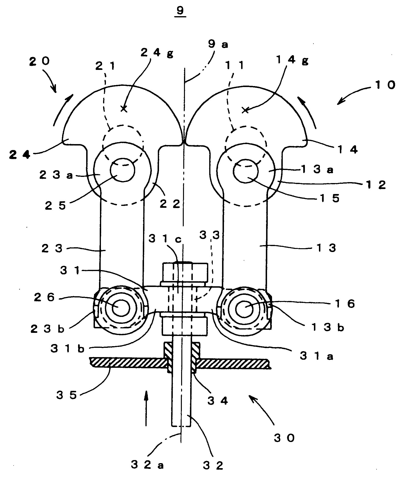
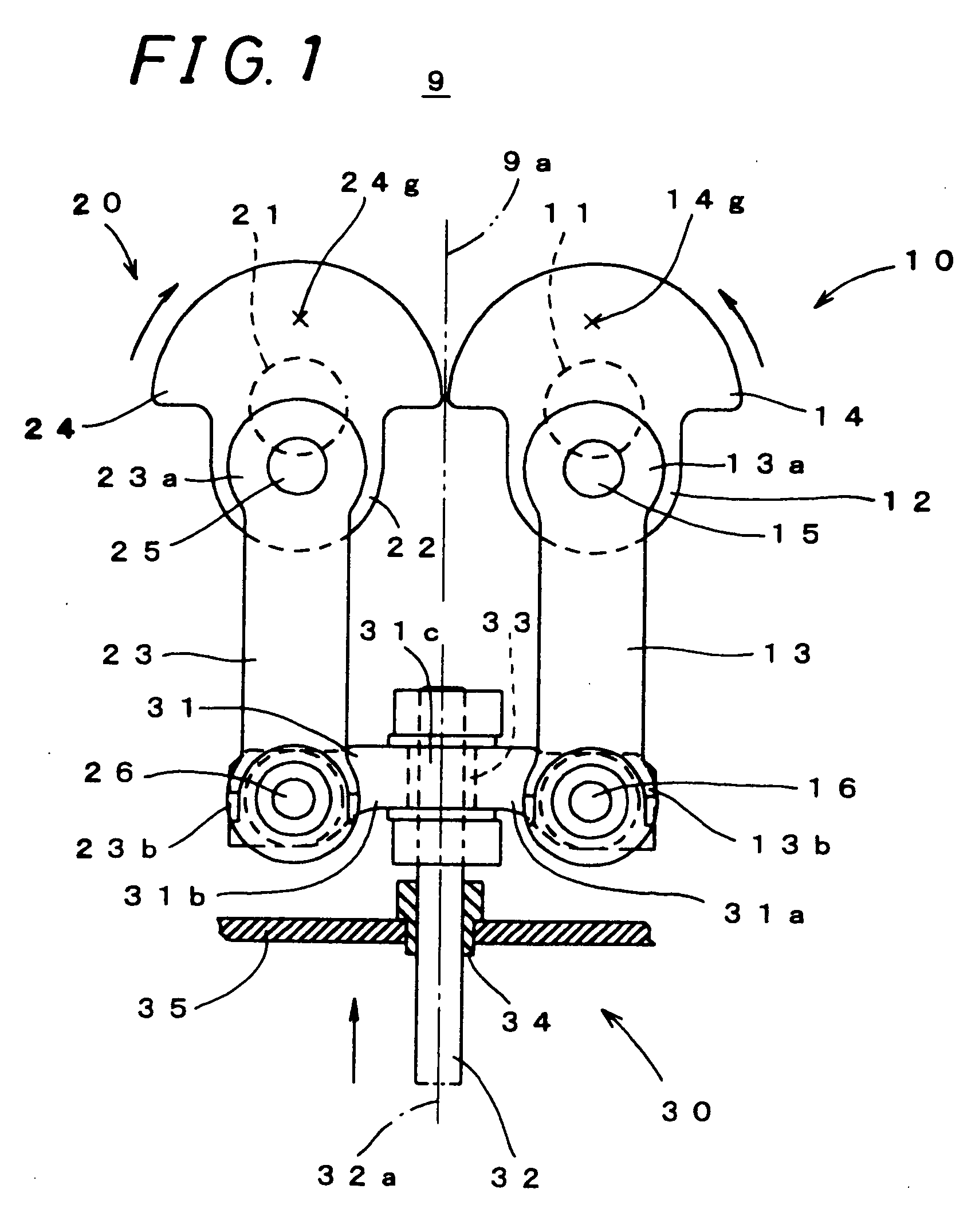
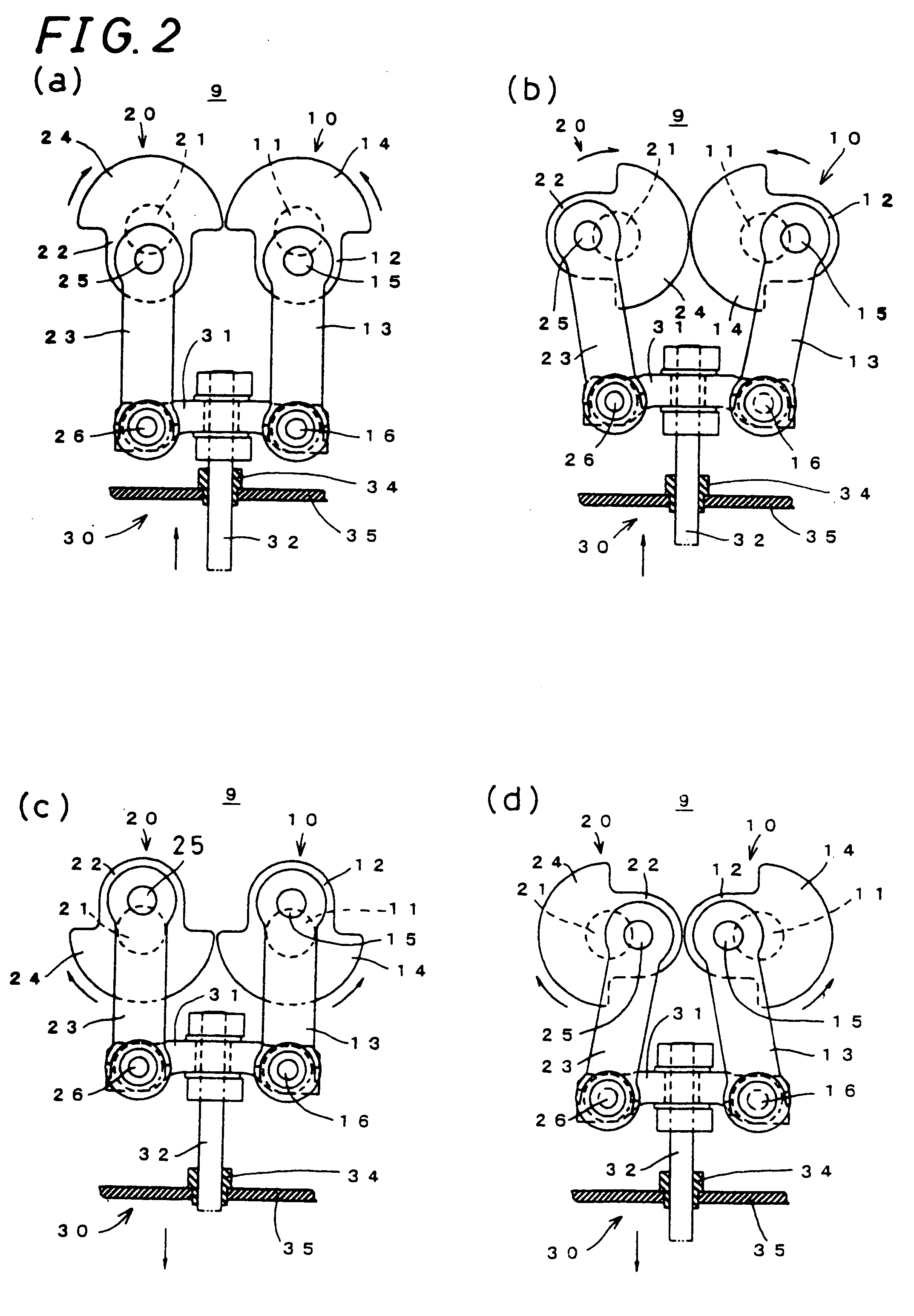
[0044]FIG. 1 shows a schematic constitution of a vibration damping apparatus for reciprocating drive 9 according to one embodiment of the invention. The vibration damping apparatus for reciprocating drive 9 is a damping apparatus as to the vibration occurring upon conversion of rotary motion into reciprocal motion in order to reciprocally drive a cutting blade by a cutting head of a cutter, including a first conversion mechanism 10, a second conversion mechanism 20 and a combining mechanism 30. The vibration damping apparatus for reciprocating drive 9 in this embodiment is constructed symmetric with respect to a virtual plane 9a. Namely, the first conversion mechanism 10 and the second conversion mechanism 20 are in a mirror relationship with each other with respect to the virtual plane 9a. The combining mechanism 30 is to extract and combine together on-virtual-plane 9a components out ...


PUM

PropertyMeasurementUnit
massaaaaaaaaaa
massaaaaaaaaaa
angle of rotationaaaaaaaaaa

Abstract

A vibration damping device that damps vibration produced during the conversion of rotational motion into reciprocal motion. The damping is performed using a simple structure, and the device can be easily downsized. A first converting mechanism and a second converting mechanism are symmetrically arranged with an imaginary plane as a plane of symmetry, a first rotating shaft and a second rotating shaft rotate opposite to each other at a constant speed, and the rotational motion is converted into reciprocal motion by a first crank rod and a second crank rod. As a result, forces in a horizontal direction balance. The total of mass acting on gravity centers of a first balancer and a second balancer is approximately equal to the total of mass reciprocally driven by a first driving shaft and a second driving shaft. Further, both gravity centers are positioned so as to be opposed at 180 degrees to the first driving shaft and second driving shaft across the axes of the first rotating shaft and second rotating shaft. As a consequence, the forces in the direction of an axis can be balanced. Because the forces are balanced, vibration generation is suppressed.

Description

TECHNICAL FIELD [0001] The present invention relates to a vibration damping apparatus for reciprocating drive for damping vibration occurring upon conversion of rotary motion into fast reciprocal motion in order to reciprocally drive a cutting blade of a cutter or so, and cutting head. BACKGROUND ART [0002] Conventionally, conversion mechanisms such as crank mechanisms are broadly used for conversion between rotary motion and linear reciprocal motion. Even though reciprocal motion can be directly caused, driving in one direction and then driving in the reverse direction requires a stoppage in the course thereof, making it difficult to increase the speed. By converting a continuous rotary motion caused by a motor, etc. into a reciprocal motion, it is possible to easily obtain a fast reciprocal motion. [0003]FIG. 11 shows a schematic structure of a cutter 1 requiring a fast reciprocal motion converted from a rotary motion for cutting. In the cutter 1, a cutting blade 6 is reciprocally...

Claims


Application Information

Patent Timeline
Patent Type & Authority Applications(United States)
IPC IPC(8): F16F15/24B62D5/08B26D7/08B26F1/38F16F15/22F16F15/26
CPCB26D7/08B26F1/382Y10T74/18152F16F15/265Y10T74/18208F16F15/22Y10T83/8824Y10T83/8843Y10T83/8844B26D1/38F16F15/26F16H21/18
Inventor IKOMA, KENJI
Owner SHIMA SEIKI MFG LTD
Learn More