
Composite material vibrator

a technology of composite materials and vibrators, which is applied in the direction of mechanical vibration separation, piezoelectric/electrostrictive devices, device material selection, etc., can solve the problems of difficult to reduce the size of the component, difficult to reduce and the thickness of the acoustic wave filter is also complex, and achieves easy to reduce the size and size. , the effect of simple structur

Inactive Publication Date: 2009-10-29
MURATA MFG CO LTD
View PDF1 Cites 0 Cited by
  • Summary
  • Abstract
  • Description
  • Claims
  • Application Information

AI Technical Summary

Benefits of technology

[0016]In order to overcome the problems described above, preferred embodiments of the present invention provide a composite material vibrator that has a relatively simple structure, that can be supported without hardly affecting the vibration characteristics of the vibrating component, that can be easily reduced in size, and that has excellent electrical characteristics.
[0025]According to the composite material vibrator of a preferred embodiment of the present invention, the reflective layer can be formed by merely curing a resin and a plurality of material layers need not be laminated. Consequently, the production process can be simplified. Since the resin used in the reflective layer also has adhesiveness, the reduction in thickness, the reduction in size, and the reduction in cost of the composite material vibrator can be achieved. Furthermore, since the reflective layer of the composite material vibrator according to various preferred embodiments of the present invention have a low sound velocity and a low damping, electrical characteristics of the composite material vibrator can be improved.

Problems solved by technology

Therefore, is has been difficult to reduce the size of the component and to reduce the cost.
Therefore, it is difficult to reduce the size, in particular, the thickness of the acoustic wave filter.
The production process is also complex.
However, when the reflective layers are formed using an epoxy resin, the piezoelectric element cannot necessarily be supported mechanically without suppressing a decrease in electrical characteristics of the piezoelectric element.
In other words, even when the holding components are connected to the piezoelectric element with the reflective layers therebetween, it may be difficult to obtain satisfactory electrical characteristics.

Method used


Image

  • Composite material vibrator
  • Composite material vibrator
  • Composite material vibrator

Examples


Embodiment Construction

[0030]A composite material vibrator according to a preferred embodiment of the present invention will now be described.

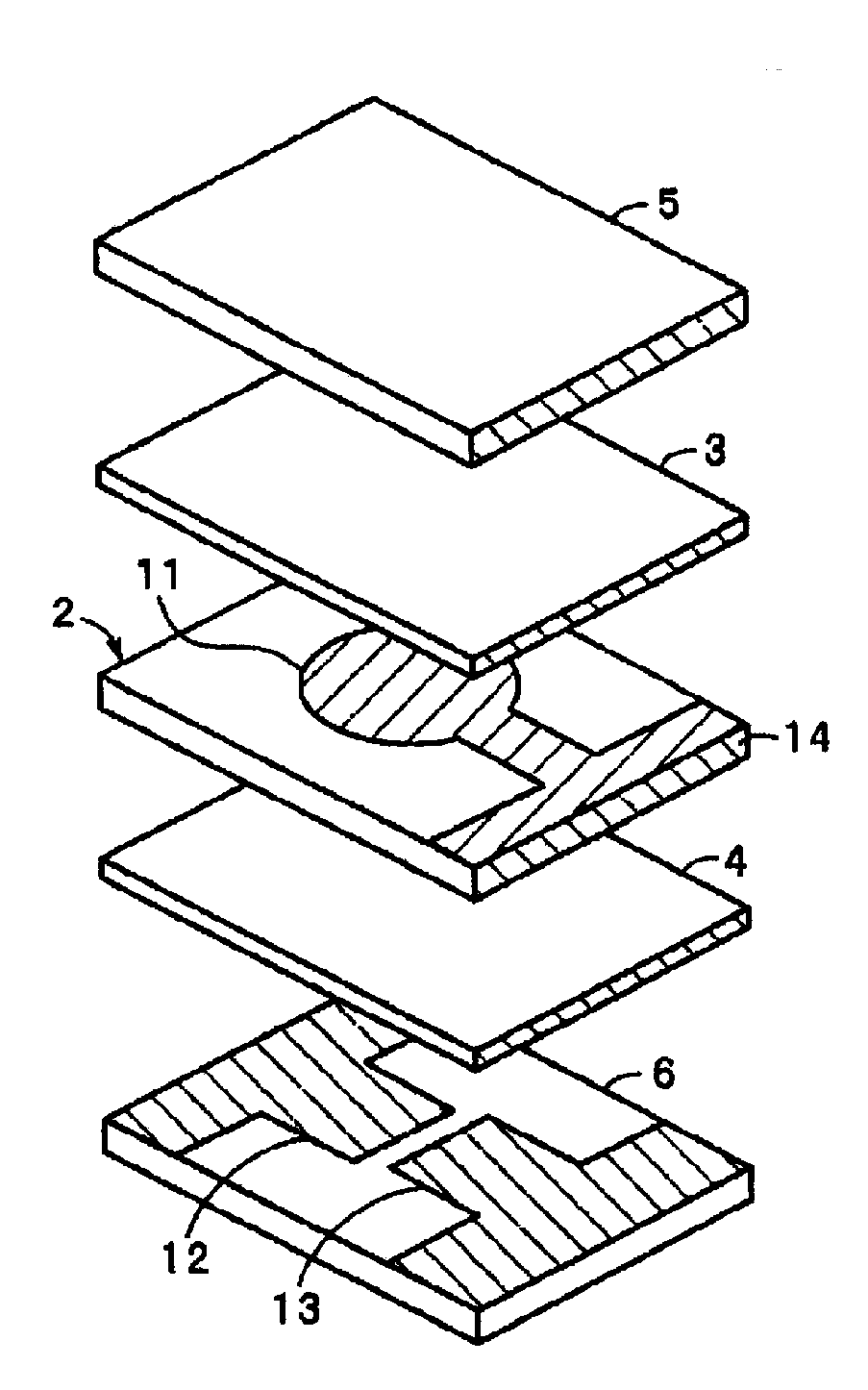
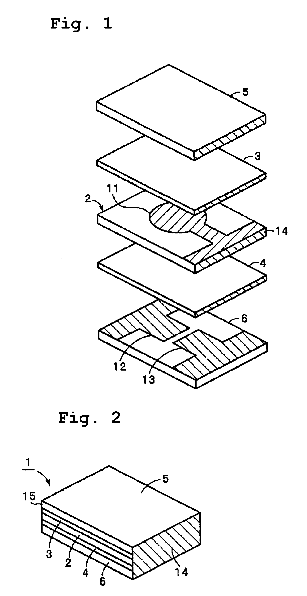
[0031]FIG. 1 is an exploded perspective view of a composite material vibrator according to a first preferred embodiment of the present invention, and FIG. 2 is a perspective view showing the appearance thereof.

[0032]In a composite material vibrator 1 of the present preferred embodiment, a piezoelectric resonator 2 is preferably used as a vibrating component, for example. The piezoelectric resonator 2 preferably includes a substantially rectangular lead zirconate titanate piezoelectric ceramic plate. This ceramic plate is subjected to a polarization treatment in the thickness direction. An excitation electrode 11 is provided at the approximate center of the upper surface of the ceramic plate. Although not shown in FIG. 1, another excitation electrode is provided at the approximate center of the lower surface of the ceramic plate. The excitation electrode 11 and the o...


PUM


Abstract

A composite material vibrator includes a vibrating component that is composed of a material having a first acoustic impedance Z1 and that serves as a vibration source, a reflective layer that is composed of a cured product of a resin composition including at least a curable resin curable by heat, a curing agent, and a silicone compound, the cured product having a second acoustic impedance Z2 that is lower than the first acoustic impedance Z1 and that is connected to the vibrating component, and a holding component that is composed of a material having a third acoustic impedance Z3 that is higher than the second acoustic impedance Z2 and that is connected to surface of the reflective layer, the surface being opposite to the surface connected to the vibrating component, wherein vibration propagated from the vibrating component to the reflective layer is reflected at the interface between the reflective layer and the holding component.

Description

BACKGROUND OF THE INVENTION[0001]1. Field of the Invention[0002]The present invention relates to a composite material vibrator in which a plurality of elements composed of materials having different acoustic impedances are combined. For example, the present invention relates to a composite material vibrator in which reflective layers having a low sound velocity and a low damping are connected to a vibrating component such as a piezoelectric element.[0003]2. Description of the Related Art[0004]As piezoelectric resonating components constituting a piezoelectric resonator, a piezoelectric filter, or the like, a component prepared by laminating case substrates on and under a piezoelectric vibrating element has been widely used. In such a case, a space for allowing for free, uninhibited vibration of the piezoelectric vibrating portion of the piezoelectric element must be provided in the laminate. For this purpose, the following methods have been used. In one method, a recess for forming ...

Claims


Application Information

Patent Timeline
Patent Type & Authority Applications(United States)
IPC IPC(8): H03H9/17B06B1/06H03H9/02H03H9/05H03H9/10H03H9/58
CPCB06B1/0644H03H9/0211H03H9/177H03H9/1035H03H9/0561H03H9/17H03H3/02H10N30/00H10N30/85
Inventor YAMADA, YUYAKAWAKAMI, AKIHIKOMATSUSHITA, KOJIUCHIDA, SHINSUKE
Owner MURATA MFG CO LTD
Learn More