Shifting device
a technology of shifting device and rotating direction, which is applied in the direction of gearing control, control device, gearing element, etc., can solve the problems of difficult water exposure prevention measures, easy temperature change in the detection of shifting direction in rotational direction, etc., and achieves simplified structure, easy reduction in size, the effect of simplifying structur
- Summary
- Abstract
- Description
- Claims
- Application Information
AI Technical Summary
Benefits of technology
Problems solved by technology
Method used
Image
Examples
first embodiment
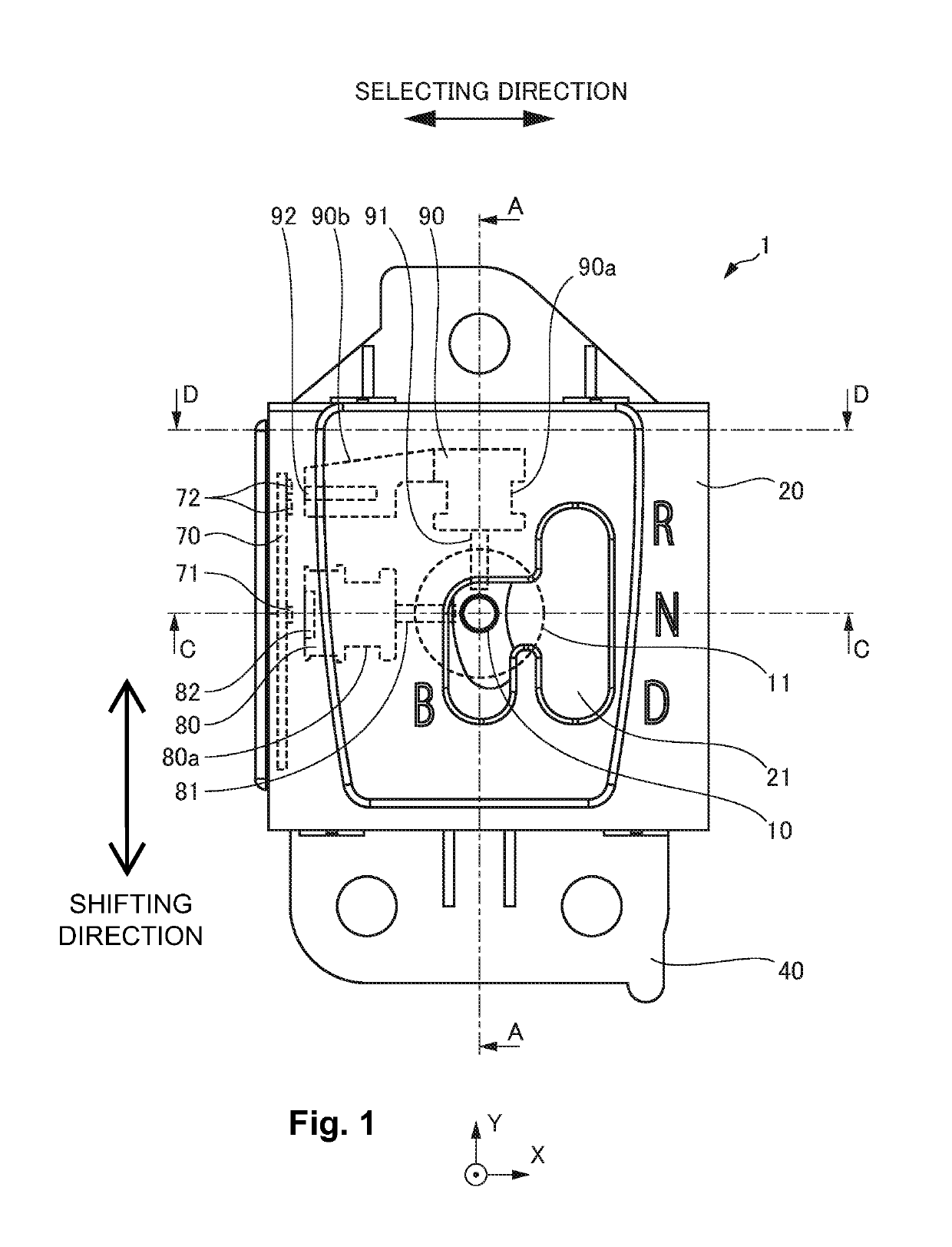
[0063]FIG. 1 is an upper view illustrating an embodiment of a shifting device 1 according to the present invention. In FIG. 1, a part of components are shown transparent.
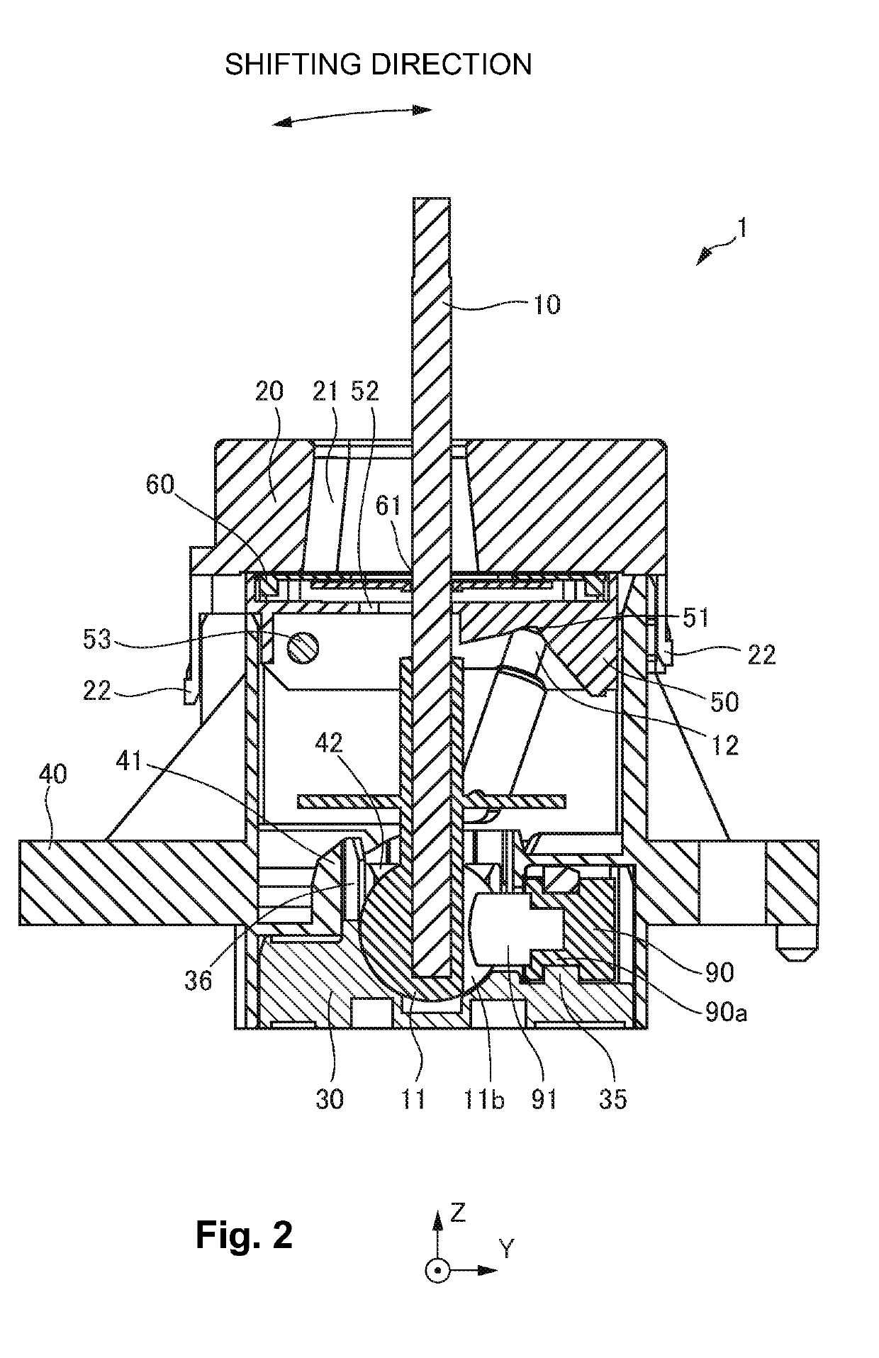
[0064]FIG. 2 is a sectional view of the shifting device 1 taken along line indicated by an arrow A-A in FIG. 1.
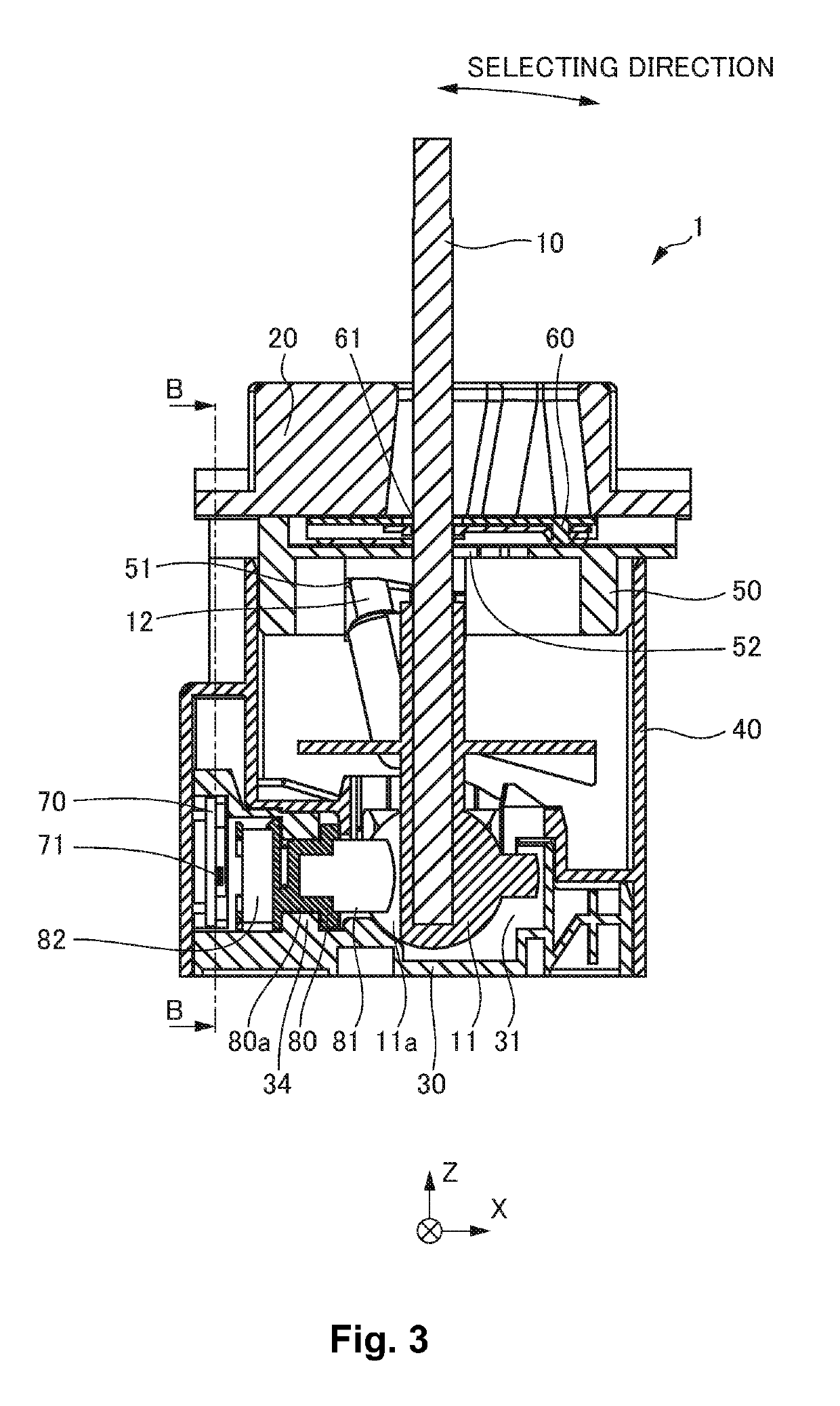
[0065]FIG. 3 is a sectional view of the shifting device 1 taken along line indicated by an arrow C-C in FIG. 1.
[0066]FIG. 4 is a sectional view of the shifting device 1 taken along line indicated by an arrow D-D an in FIG. 1.
[0067]FIG. 5 is a sectional view of the shifting device 1 taken along line indicated by an arrow B-B in FIG. 3.
[0068]FIG. 6 is a perspective view illustrating a part of the components constituting the shifting device 1.
[0069]It should be noted that the drawings listed below including FIG. 1 to FIG. 6 are schematic illustration, and sizes and shapes of the components are shown emphasized and not to scale as needed in order to facilitate understanding.
[0070]Further, while reference is mad...
second embodiment
[0126]FIG. 17 is a perspective view illustrating an embodiment of a shifting device 2 according to the present invention.
[0127]FIG. 18 is a perspective view of the shifting device 2 with a knob 214 and a bezel 220 in FIG. 17 are removed.
[0128]FIG. 19 is an exploded perspective view of the shifting device 2.
[0129]FIG. 20 is a perspective view of the shifting device 2 seen from a different angle.
[0130]FIG. 21 is a perspective view of the shifting device 2 with the knob 214 and the bezel 220 in FIG. 20 are removed.
[0131]FIG. 22 is an upper view of the shifting device 2 with the knob 214 is removed.
[0132]FIG. 23 is a sectional view of the shifting device 2 taken along line indicated by an arrow H-H in FIG. 22.
[0133]FIG. 24 is a sectional view of the shifting device 2 taken along line indicated by an arrow I-I in FIG. 22.
[0134]FIG. 25 is a sectional view of the shifting device 2 taken along line indicated by an arrow J-J in FIG. 22.
[0135]FIG. 26 is an upper view of the shifting device 2 ...
third embodiment
[0171]FIG. 28 is a perspective view illustrating an embodiment of a shifting device 3 according to the present invention.
[0172]In FIG. 28, a bezel 320 is omitted and not shown.
[0173]Further, while an XYZ orthogonal coordinate system is provided in the drawings listed below including FIG. 28 in order to facilitate illustration and understanding, this is not for indicating absolute coordinates, but merely for showing common orientation in the drawings.
[0174]FIG. 29 is a view illustrating the shifting device 3 with a bezel 320 attached.
[0175]FIG. 30 is a perspective view illustrating a main part of the shifting device 3.
[0176]FIG. 31 is a perspective view illustrating the main part of the shifting device 3.
[0177]FIG. 32 is a perspective view illustrating the main part of the shifting device 3.
[0178]FIG. 33 is a perspective view illustrating a restricting member 356.
[0179]FIG. 34 is a perspective view illustrating a state in which a restricting gear 357 is removed from the restricting m...
PUM
 Abstract
Description
Claims
Application Information
 - R&D
- Intellectual Property
- Life Sciences
- Materials
- Tech Scout
- Unparalleled Data Quality
- Higher Quality Content
- 60% Fewer Hallucinations
Browse by: Latest US Patents, China's latest patents, Technical Efficacy Thesaurus, Application Domain, Technology Topic, Popular Technical Reports.
© 2025 PatSnap. All rights reserved.Legal|Privacy policy|Modern Slavery Act Transparency Statement|Sitemap|About US| Contact US: help@patsnap.com


