Preheating/precooling heat exchanger

a heat exchanger and pre-cooling technology, applied in the direction of defrosting, separation processes, domestic cooling apparatus, etc., can solve the problems of skip in a high-temperature environment, the dryer will occupy too much room of the compressed air purifying system, etc., to achieve effective reduction of the burden on the coolant compressor, enhanced condensing power, and high environmental temperature

Inactive Publication Date: 2006-08-03
CHIEN MING KUN
View PDF7 Cites 1 Cited by
  • Summary
  • Abstract
  • Description
  • Claims
  • Application Information

AI Technical Summary

Benefits of technology

[0004] It is therefore a primary object of the present invention to provide a preheating / precooling heat exchanger including a preheating / precooling exchanger and an evaporator. The preheating / precooling exchanger has an intake and an exhaust port for compressed air to come in and go out. The intake is connected with an intake duct circulated inside the preheating / precooling exchanger to communicate with the evaporator. A condensing pipe is circulated inside the evaporator for heat exchange between the compressed air and a coolant in the condensing pipe and for condensing the vapor in the compressed air into water drops. The evaporator has an inlet and an outlet. The inlet is connected to the intake duct of the preheating / precooling exchanger, whereby the compressed air can go from the intake duct into the evaporator. The outlet communicates with the preheating / precooling exchanger, whereby the compressed air can flow back into the preheating / precooling exchanger. The compressed air cooled by the evaporator will further flow back into the preheating / precooling exchanger. Therefore, the temperature of the original high-temperature compressed air in the intake duct of the preheating / precooling exchanger 1 will be lowered. Accordingly, the temperature of the compressed air going into the evaporator is lowered so that the evaporator can reduce the temperature of the compressed air to dew point without great power. Therefore, the condensing power is enhanced to effectively lower the burden on the coolant compressor. Accordingly, the skip of the heat exchanger caused by too high environmental temperature can be avoided.

Problems solved by technology

Accordingly, the drier will occupy too much room of the compressed air purifying system.
This often leads to the problem of skip in a high-temperature environment such as in a summer day.

Method used


Image

  • Preheating/precooling heat exchanger
  • Preheating/precooling heat exchanger
  • Preheating/precooling heat exchanger

Examples


Embodiment Construction

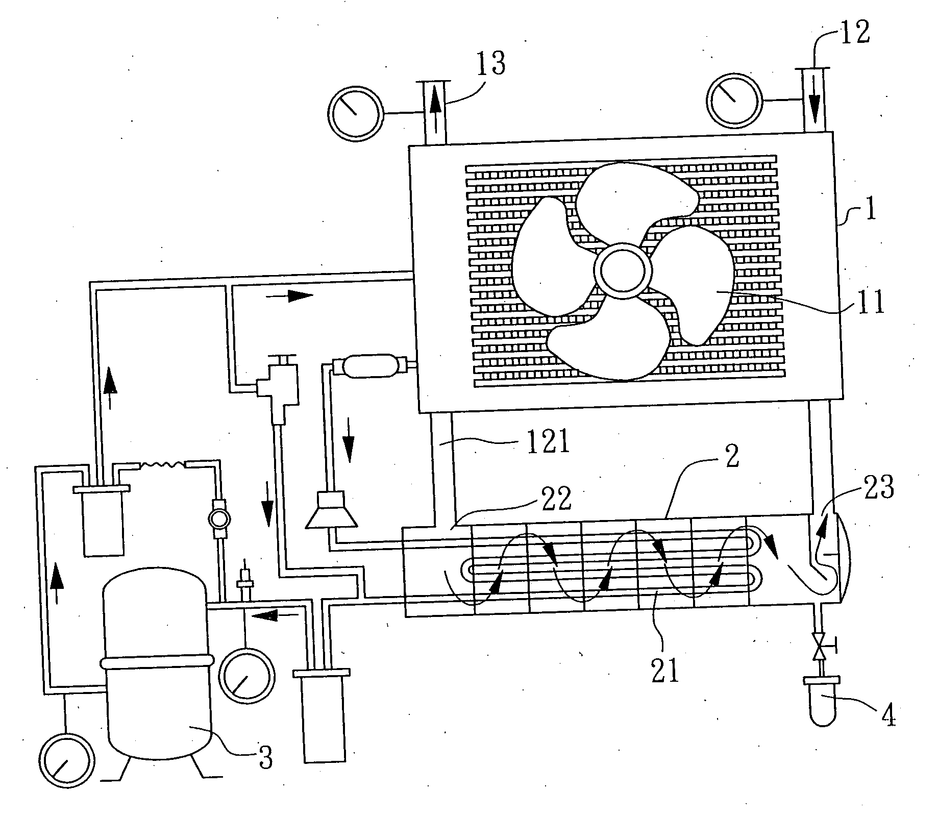
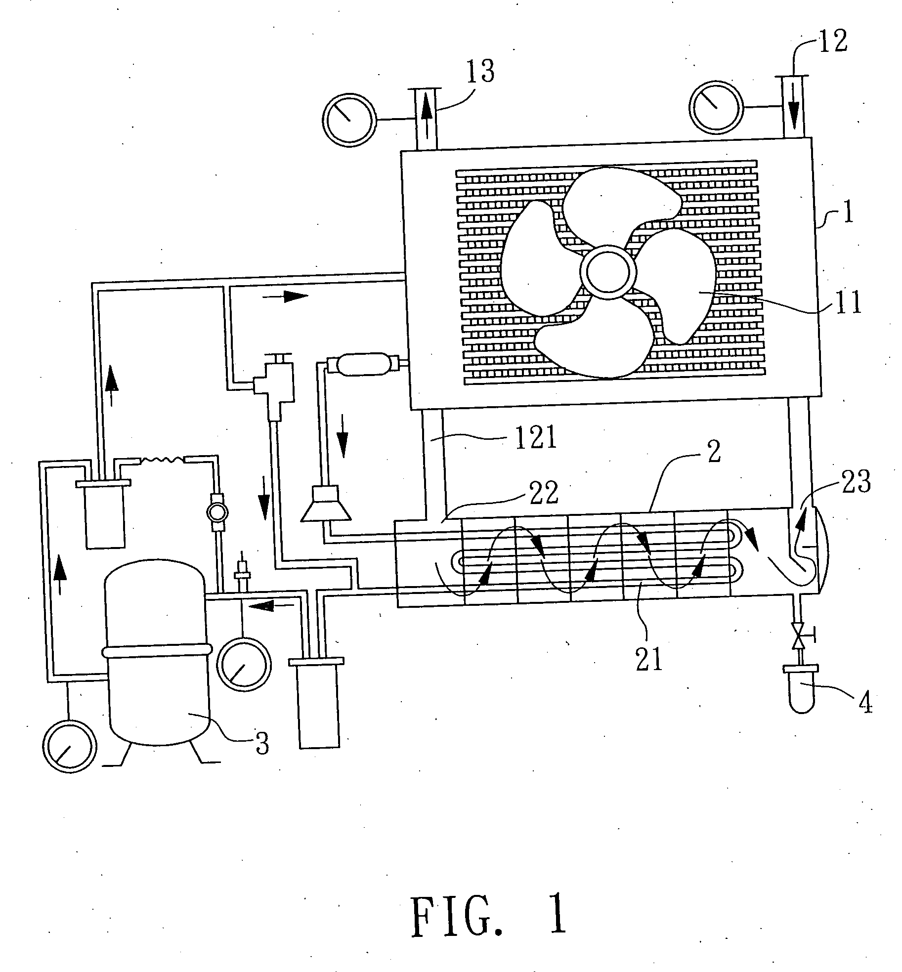
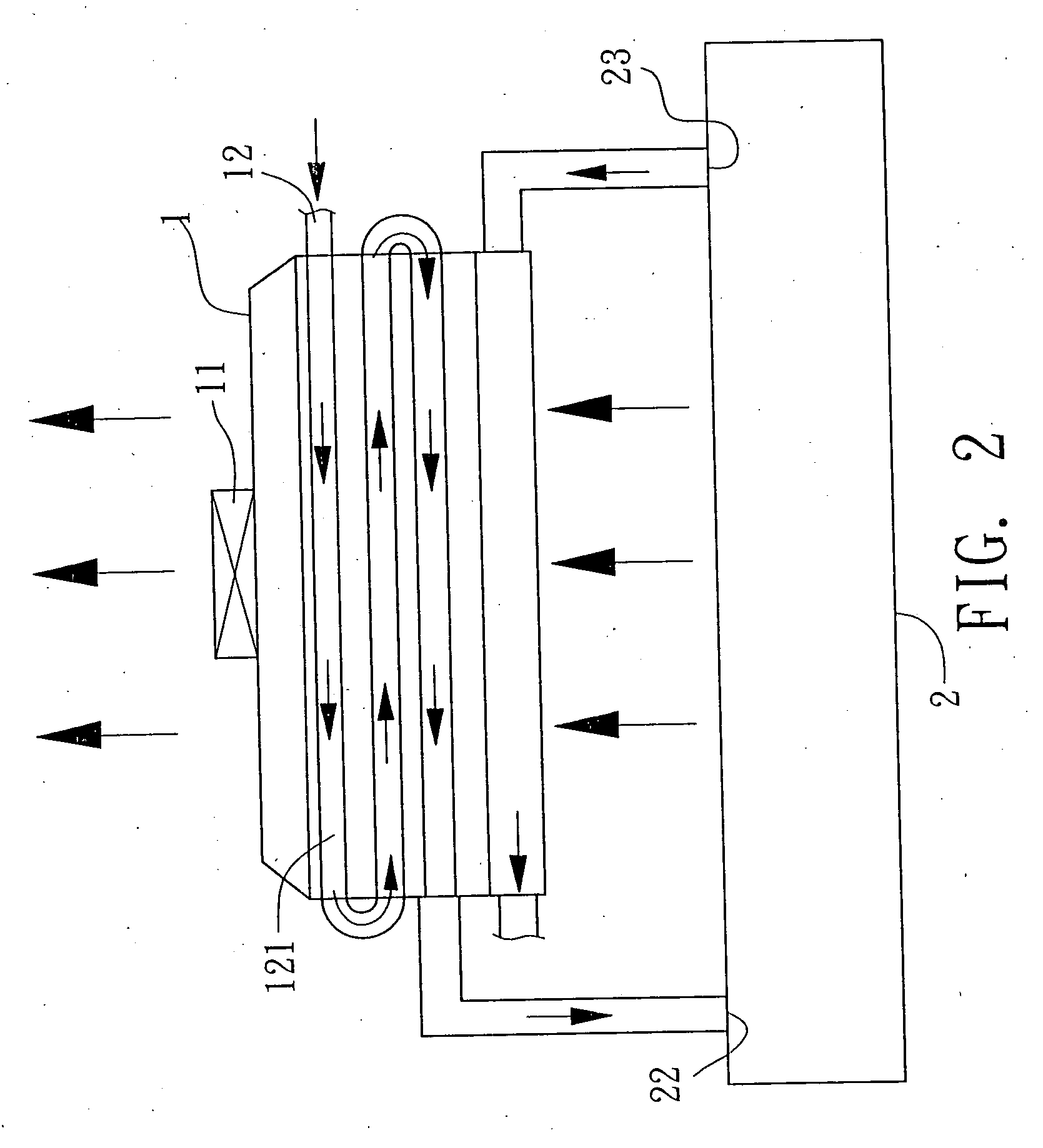
[0012] Please refer to FIGS. 1 and 2. The preheating / precooling heat exchanger of the present invention includes a preheating / precooling exchanger 1, an evaporator 2 and a coolant compressor 3. At least one fan 11 is disposed on outer side of the preheating / precooling exchanger 1. The preheating / precooling exchanger 1 has an intake 12 and an exhaust port 13. The intake 12 is connected with an intake duct 121 circulated inside the preheating / precooling exchanger 1 to communicate with the evaporator 2. A condensing pipe 21 is circulated inside the evaporator 2. The coolant compressor 3 supplies coolant for the condensing pipe 21. The evaporator 2 has an inlet 22 and an outlet 23. The inlet 22 is connected to the intake duct 121 of the preheating / precooling exchanger 1, whereby the compressed air goes from the intake duct 121 into the evaporator 2. The outlet 23 communicates with the preheating / precooling exchanger 1, whereby the compressed air can flow back into the preheating / precool...


PUM


Abstract

A preheating/precooling heat exchanger including a preheating/precooling exchanger and an evaporator. The preheating/precooling exchanger has an intake and an exhaust port for compressed air to come in and go out. The intake is connected with an intake duct circulated inside the preheating/precooling exchanger to communicate with the evaporator. A condensing pipe is circulated inside the evaporator for heat exchange between the compressed air and a coolant in the condensing pipe and for condensing the vapor in the compressed air into water drops. The evaporator has an inlet and an outlet. The inlet is connected to the intake duct of the preheating/precooling exchanger, whereby the compressed air can go from the intake duct into the evaporator. The outlet communicates with the preheating/precooling exchanger, whereby the compressed air can flow back into the preheating/precooling exchanger.

Description

BACKGROUND OF THE INVENTION [0001] The present invention is related to a preheating / precooling heat exchanger with higher heat exchange efficiency and reduced volume. [0002] In a conventional compressed air purifying system, a wind-cooling drier is disposed for cooling and drying the compressed air so as to prevent the system from being affected by the humidity and temperature of the compressed air. FIG. 3 shows a conventional wind-cooling drier including a precooler 6, an air heat exchanger 7, an evaporator 8 and a condenser 9. The temperature of the compressed air is first lowered to normal temperature by the precooler 6. Then the compressed air goes into the air heat exchanger 7 to slightly precool the compressed air and remove part of the vapor. Then the compressed air further goes into the evaporator 8 for heat exchange between the compressed air and the coolant. The condenser 9 sends the coolant into the evaporator 8 to lower the temperature of the compressed air to dew point ...

Claims


Application Information

Patent Timeline
Patent Type & Authority Applications(United States)
IPC IPC(8): F25D17/06F25D21/00F25D9/00
CPCB01D53/26
Inventor CHIEN, MING KUN
Owner CHIEN MING KUN
Why Eureka
Try Eureka