

Drive engagement apparatus
- Summary
- Abstract
- Description
- Claims
- Application Information
AI Technical Summary
Benefits of technology
Problems solved by technology
Method used
Image

Examples
first embodiment
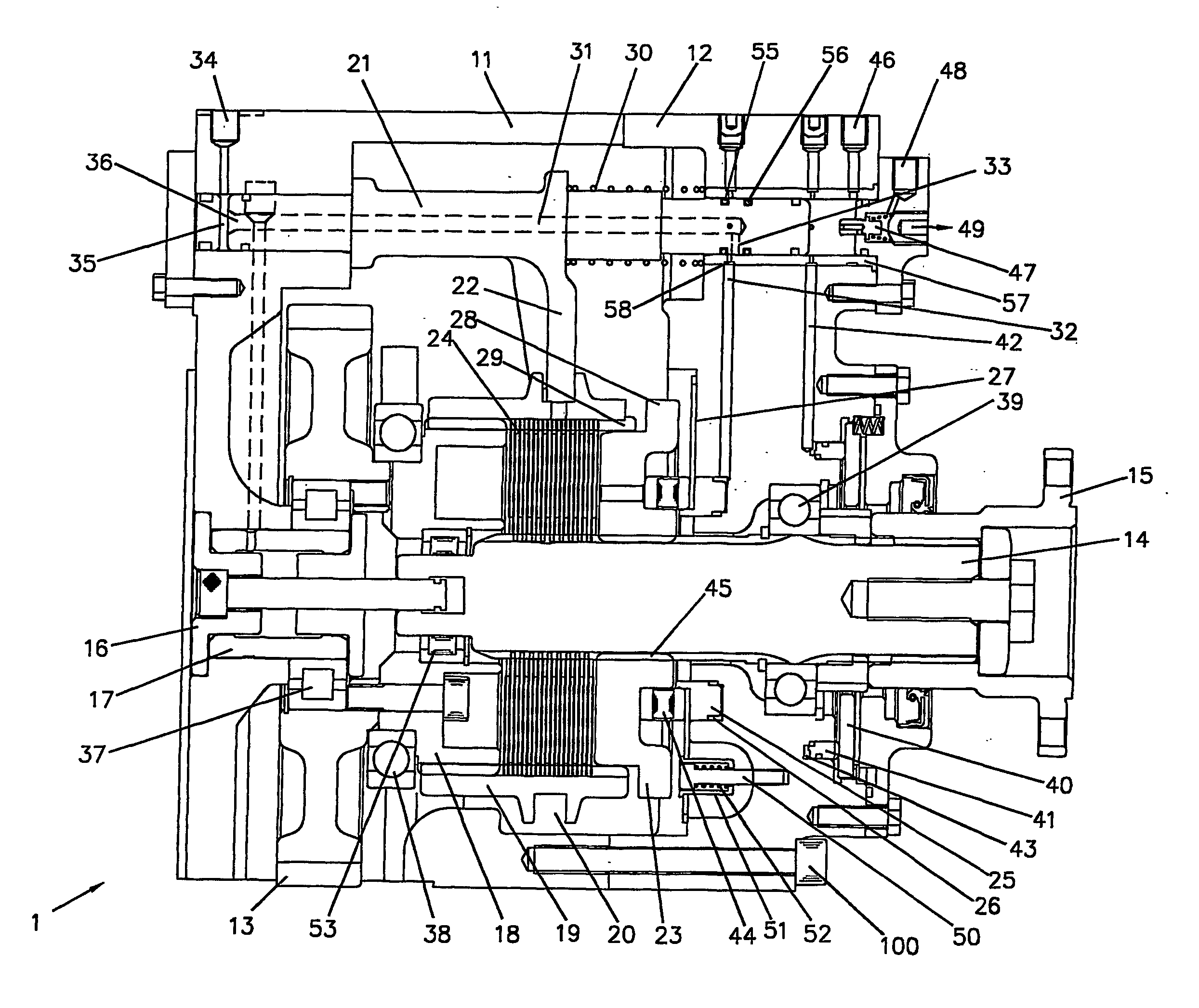
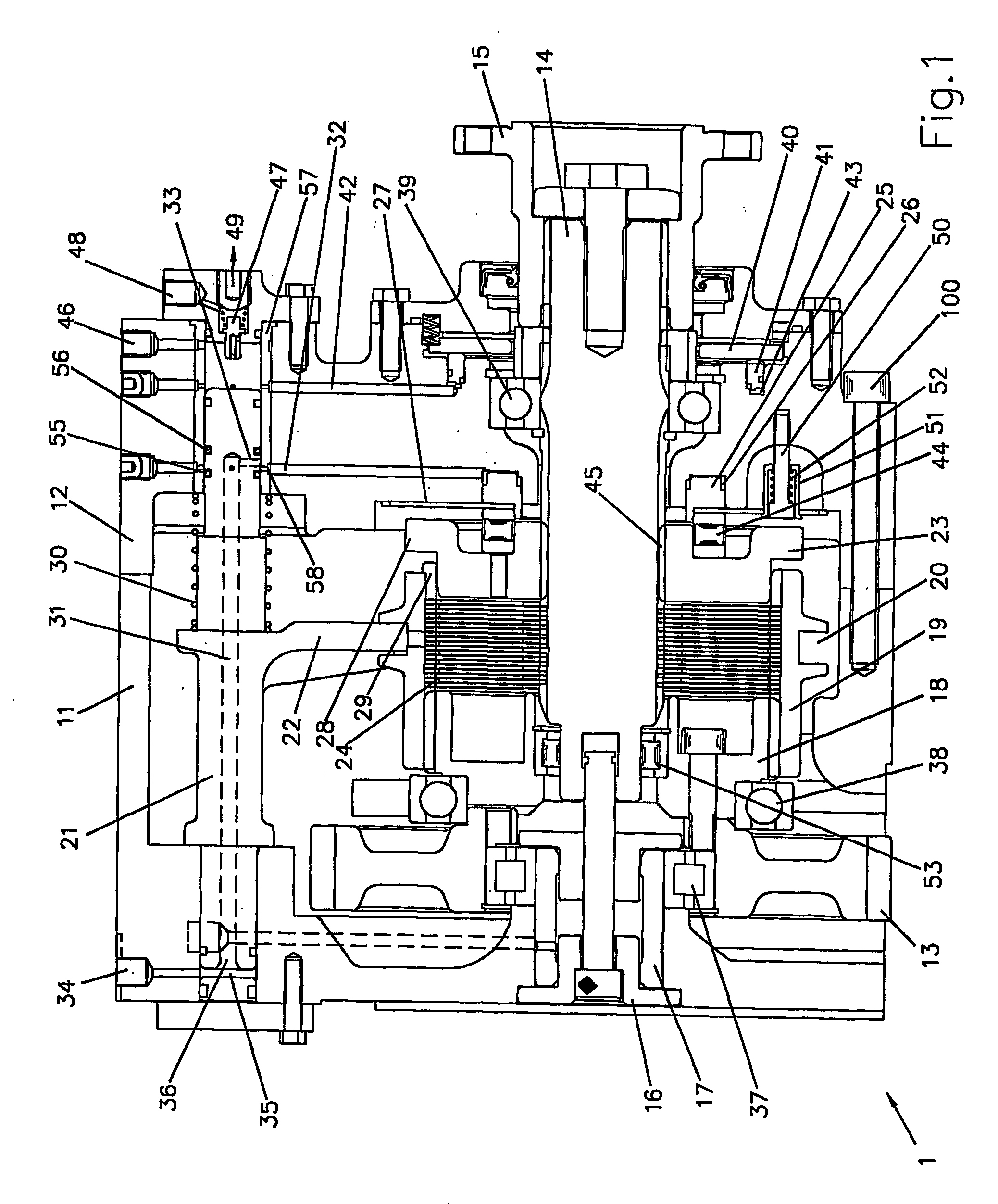
[0033] the drive arrangement 1 of the invention shown in FIG. 1 has a housing consisting of two parts 11, 12 fixed together using e.g. bolt 100. The housing defines a space in which the mechanism of the invention is located. A driving gear 13 is rotatably mounted in the housing by means of roller bearing 37, which is located on shaft 17 fixed to stub 16 on the end wall of the housing. Driving gear 13 is externally splined to be permanently engaged to a rotating member (not shown) of an engine. Thus, when the engine is running, driving gear 13 rotates. Extension member 18 is bolted to driving gear 13 to rotate with it. Extension member 18 is splined around its external surface. Driving sleeve 19 is internally splined, and is keyed into axially slidable engagement with the extension member 18, so that it rotates with the driving gear 13 but is axially slidable relative to the extension member 18.
[0034] The housing also holds output shaft 14 via roller bearing 39. One end of the output...
second embodiment
[0050]FIG. 4 shows a drive arrangement 2 which is the invention. It has many components in common with the arrangement shown in FIG. 1, and these components are labelled with the same reference number.
[0051] The drive arrangement shown in FIG. 4 is for smaller loads than the arrangement shown in FIG. 1. In FIG. 1, the axis of rotation of the output shaft 14 was aligned with the drive axis (i.e. the axis of rotation of the driving gear 13). In FIG. 4, the axis of rotation of the output shaft 14 makes an angle with drive axis.
[0052] Furthermore, the direction of the sleeve's 19 slide into engagement with the output dog 23 with opposite to that of the arrangement shown in FIG. 1. In FIG. 4, the sleeve 19 slides away from the element to be driven (not shown) which is attached to the output shaft 14 by the coupling 15. Thus, the piston arrangement is reversed with respect to the output shaft. The space 35 for receiving input compressed gas to move the piston 21 is now in the same housin...
third embodiment
[0057]FIG. 5a shows a drive arrangement 3 which is the invention. Like FIG. 1, the drive arrangement 3 shown in FIG. 5a is of the type where the rotation axis of the shaft 14 is aligned with the rotation axis of the driving gear 13. One difference between the drive arrangements of FIGS. 1 and 5a is the direction of axial movement of the sleeve to effect positive drive engagement. Unlike FIG. 1, in FIG. 5a, the sleeve 19 is not keyed into the extension member 18 and therefore does not rotate with the engine. Thus, when the drive arrangement 3 is in the disengaged position (shown in FIG. 5a), the sleeve 19 is at rest. This means that the friction plates 24 that are engaged with the sleeve are also at rest. In order to activate a friction drive, it is therefore necessary that the friction plates that are engaged with the shaft 14 rotate with the driving gear 13. To achieve this, the shaft 14 includes a driven part 64 that is drivably connected to and rotates with the extension member 1...
PUM
 Abstract
Description
Claims
Application Information