Forge welding of heavy duty tubulars

a forging welding and tubular technology, applied in the direction of welding equipment, manufacturing tools, non-electric welding equipment, etc., can solve the problems of high elastic, plastic and/or pseudo-plastic deformation of the tubular wall and any tubular joint, and achieve the effect of reducing the presence of abrupt stress variations

Inactive Publication Date: 2006-08-03
SHELL OIL CO
View PDF36 Cites 12 Cited by
  • Summary
  • Abstract
  • Description
  • Claims
  • Application Information

AI Technical Summary

Benefits of technology

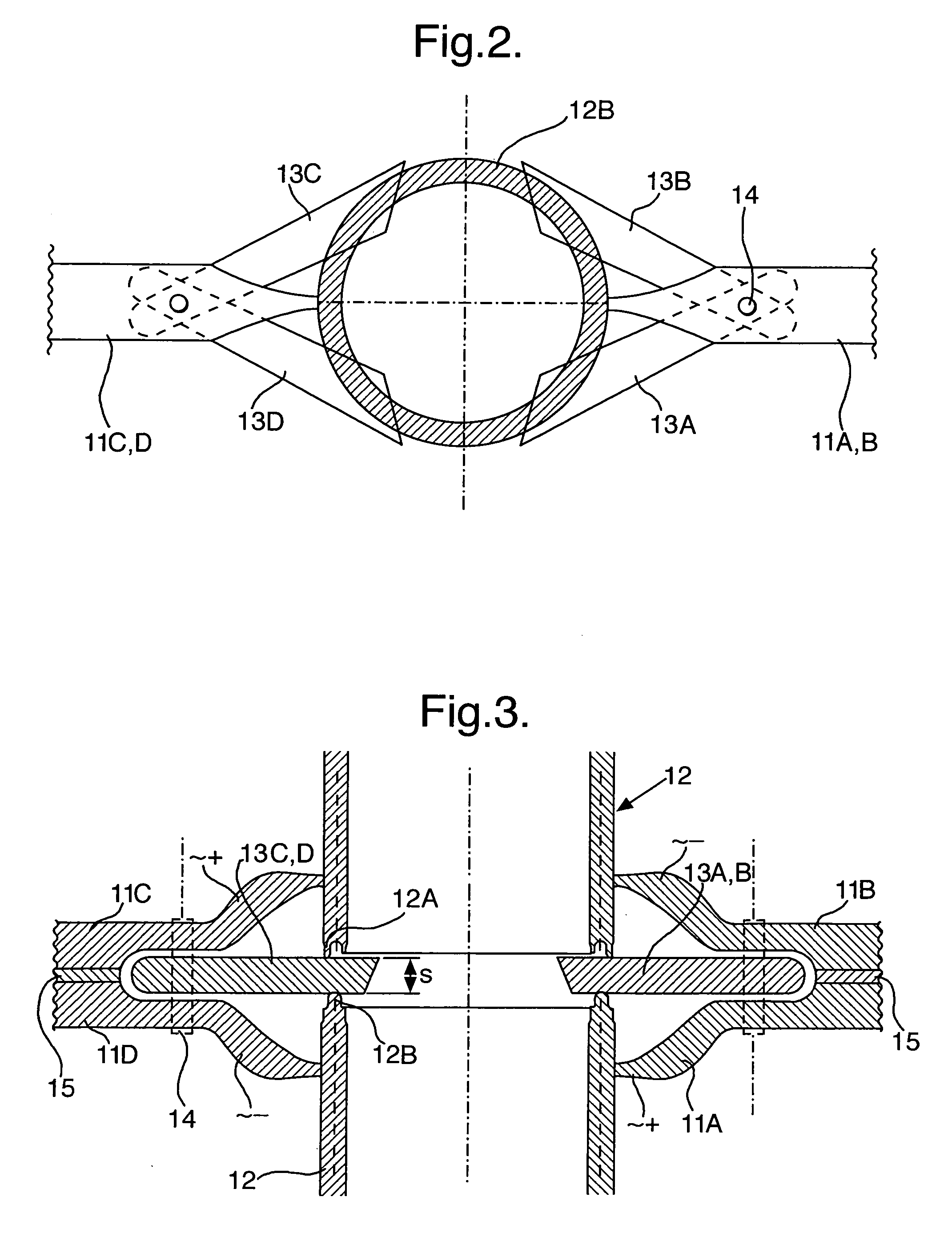
[0010] The non-planar shaped tubular ends preferably have a regular intermeshing sinusoidal or teethed shape in order to inhibit in particular shear stresses on the forge welded joint when the tubular string is twisted and / or radially expanded, while the tubular string is rotated and / or radially stretched in a cavity, such as an underground borehole.

Problems solved by technology

Thus the heavy duty tubulars may frequently be subject to large radial, tangential and / or shear stresses which cause a high elastic, plastic and / or pseudo plastic deformation of the tubular wall and any tubular joints.

Method used


Image

  • Forge welding of heavy duty tubulars
  • Forge welding of heavy duty tubulars
  • Forge welding of heavy duty tubulars

Examples


Embodiment Construction

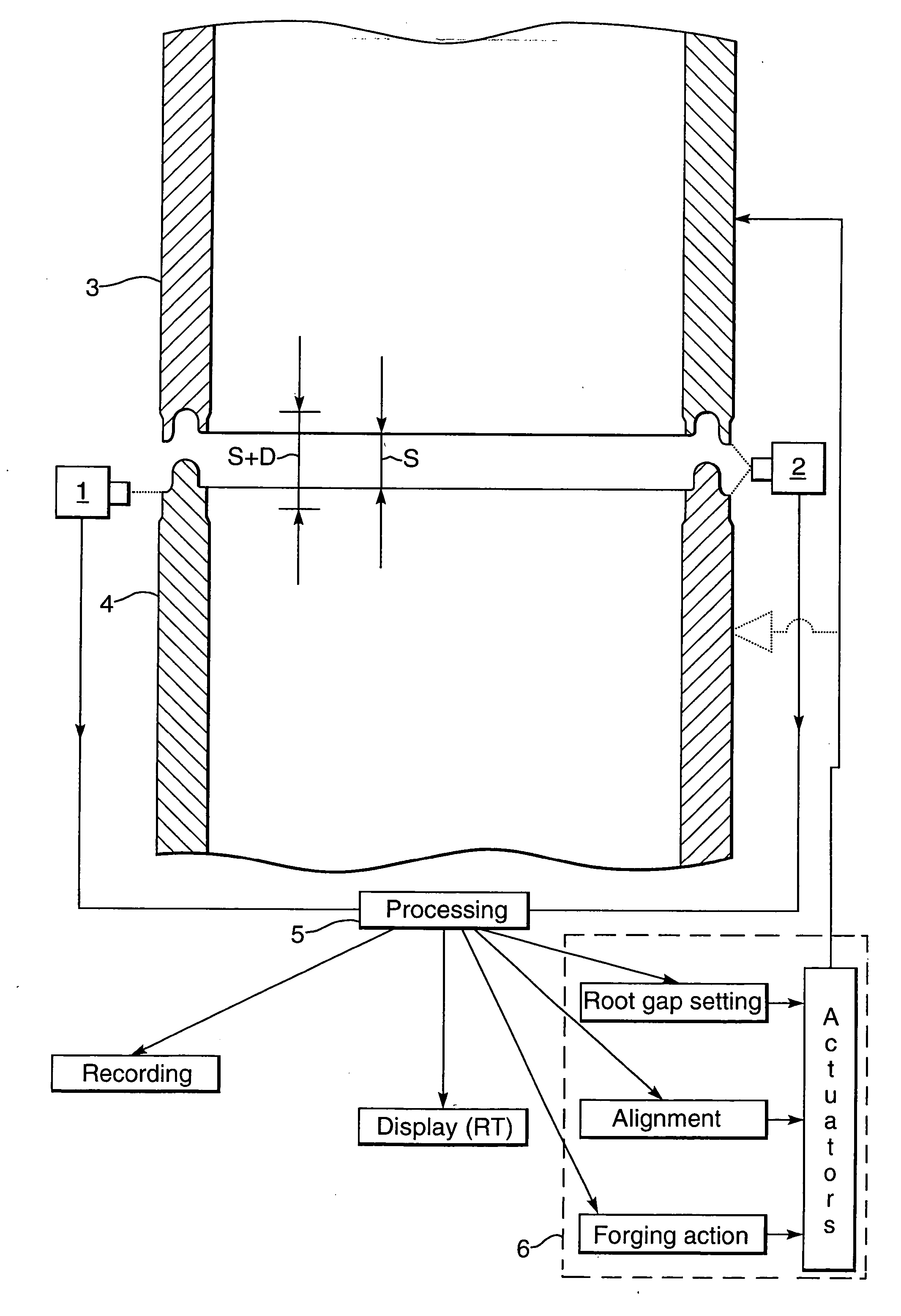
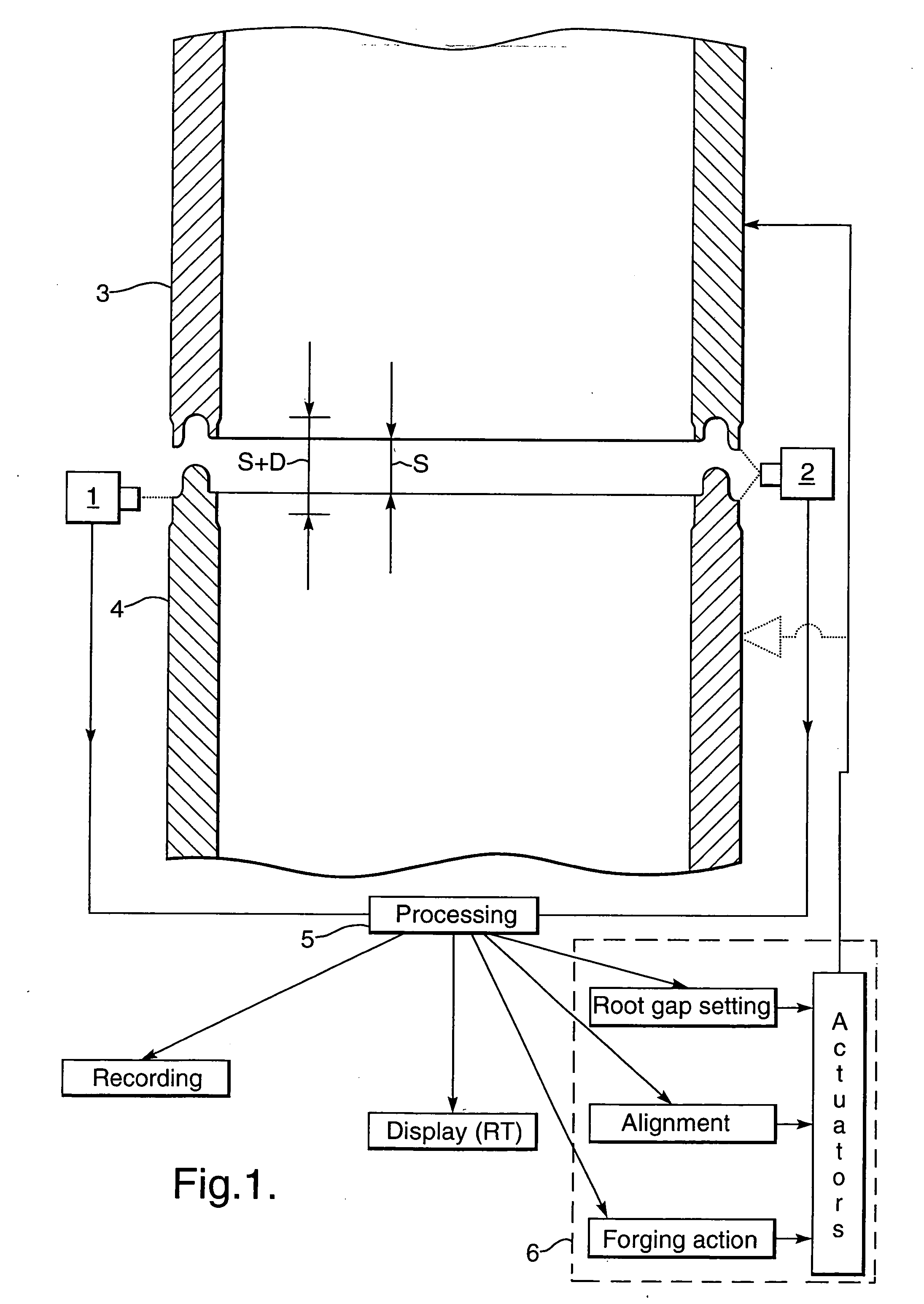
[0047] As shown in FIG. 1 the positions of the tubular ends 3 and 4 that are to be forge welded together are monitored by cameras 1 and 2 which are coupled to a camera signal processor 5 which automatically controls a gripping assembly 6, such that the spacing S between the heated tubular ends 3A and 4A is well defined during the heat up phase and the tubular ends are moved towards each other when a pyrometric control unit indicates that the tubular ends have reached a predetermined minimum and / or maximum temperature along at least a substantial part of the circumference thereof, whereupon the gripping assembly is activated to move the tubular ends 3A and 4A towards each other over a predetermined distance (S+D) which exceeds said spacing (S) with an additional distance (D) of less than a few millimeters, such that a forge weld is obtained of a substantially equal and high quality over the entire circumference of the forge welded ends and only minimal external and / or internal upsets...


PUM

PropertyMeasurementUnit
diameteraaaaaaaaaa
lengthaaaaaaaaaa
temperatureaaaaaaaaaa

Abstract

A method of joining heavy duty oilfield, well, or other tubulars includes the step of joining the tubulars by forge welding and flushing a reducing flushing gas around the heated tubular ends during at least part of the forge welding operation such that oxides are removed from the forge welded tubular ends and the amount of oxide inclusions and irregularities between the forge welded tubular ends is limited. The tubular ends may have a teethed sinusoidal or other non-planar shape to inhibit any abrupt variations of the wall strength in the welding area and / or to reduce shear forces to the forge weld when the tubulars are twisted and / or radially expanded.

Description

FIELD OF THE INVENTION [0001] The invention relates to an improved method for forge welding of heavy duty tubulars such that a welded connection of high strength and quality is obtained. BACKGROUND OF THE INVENTION [0002] Heavy duty tubulars may be formed by oilfield, well and / or other tubulars which are in use subject to high mechanical and / or thermal stresses as a result of their use in an irregular borehole or hostile on- or offshore environment. Thus the heavy duty tubulars may frequently be subject to large radial, tangential and / or shear stresses which cause a high elastic, plastic and / or pseudo plastic deformation of the tubular wall and any tubular joints. The heavy duty tubulars may be tubulars which are expanded downhole to a larger diameter and plastically deformed during the expansion process, drill pipes which may be 10 kilometers long and twisted over 30 times of the pipe circumference as a result of the torque transmitted to the drill bit and friction between the dril...

Claims


Application Information

Patent Timeline
Patent Type & Authority Applications(United States)
IPC IPC(8): B23K35/38B23K31/02B23K13/00B23K13/02B23K13/04B23K13/06B23K20/00B23K20/02B23K20/14B23K33/00
CPCB23K13/00B23K13/025B23K13/046B23K13/06B23K20/00B23K20/023B23K20/14B23K33/006
Inventor DEN BOER, JOHANNIS JOSEPHUSCOLE, ANTHONY THOMASDIMITRIADIS, KLISTHENISZIJSLING, DJURRE HANS
Owner SHELL OIL CO
Why Eureka
Try Eureka