Infrared sensor

a technology of infrared sensor and infrared light, which is applied in the field of infrared sensors, can solve the problems of insufficient coverage of metal layers, degraded sensitivity of sensors to infrared light, and decreased temperature difference between cold junctions and hot junctions, so as to improve the sensitivity of sensors

Inactive Publication Date: 2006-08-03
DENSO CORP
View PDF5 Cites 47 Cited by
  • Summary
  • Abstract
  • Description
  • Claims
  • Application Information

AI Technical Summary

Benefits of technology

[0007] In view of the foregoing problem, it is an object to provide an infrared sensor that can improve the detection sensitivity of infrared light.
[0009] Accordingly, the coverage of the infrared light reflector according to the invention may be sufficient to shield any portion of the infrared light sensing element that is not covered by the infrared light absorption film, and thereby an infrared sensor according to the invention can improve the sensitivity of the sensor to infrared light as compared with the conventional infrared sensor described above.

Problems solved by technology

That is, the differences in temperature between cold junctions and hot junctions decrease, and therefore the sensitivity of the sensor to infrared light degrades.
Particularly, according to the above-mentioned publication, since a membrane has a step portion due to the formation of the cavity, the coverage of a metal layer may be insufficient.

Method used


Image

  • Infrared sensor
  • Infrared sensor
  • Infrared sensor

Examples


first embodiment

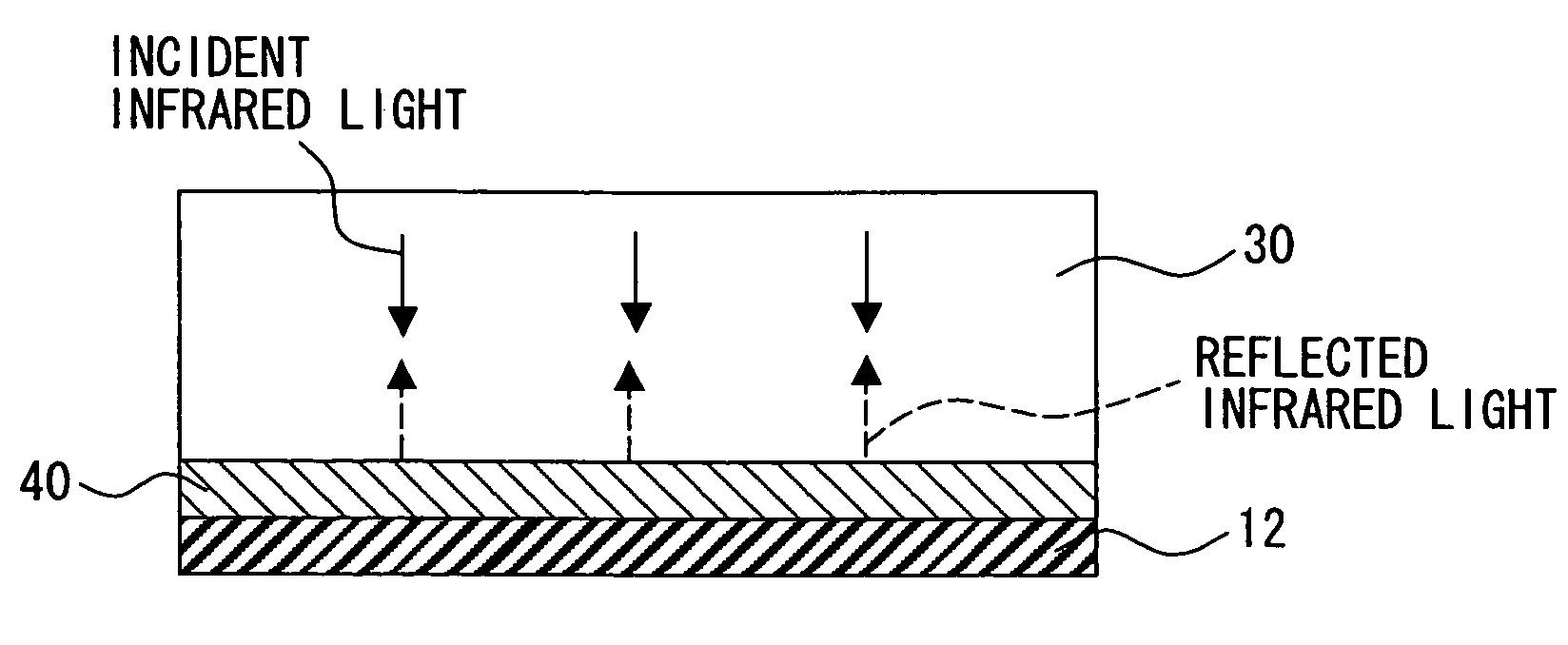
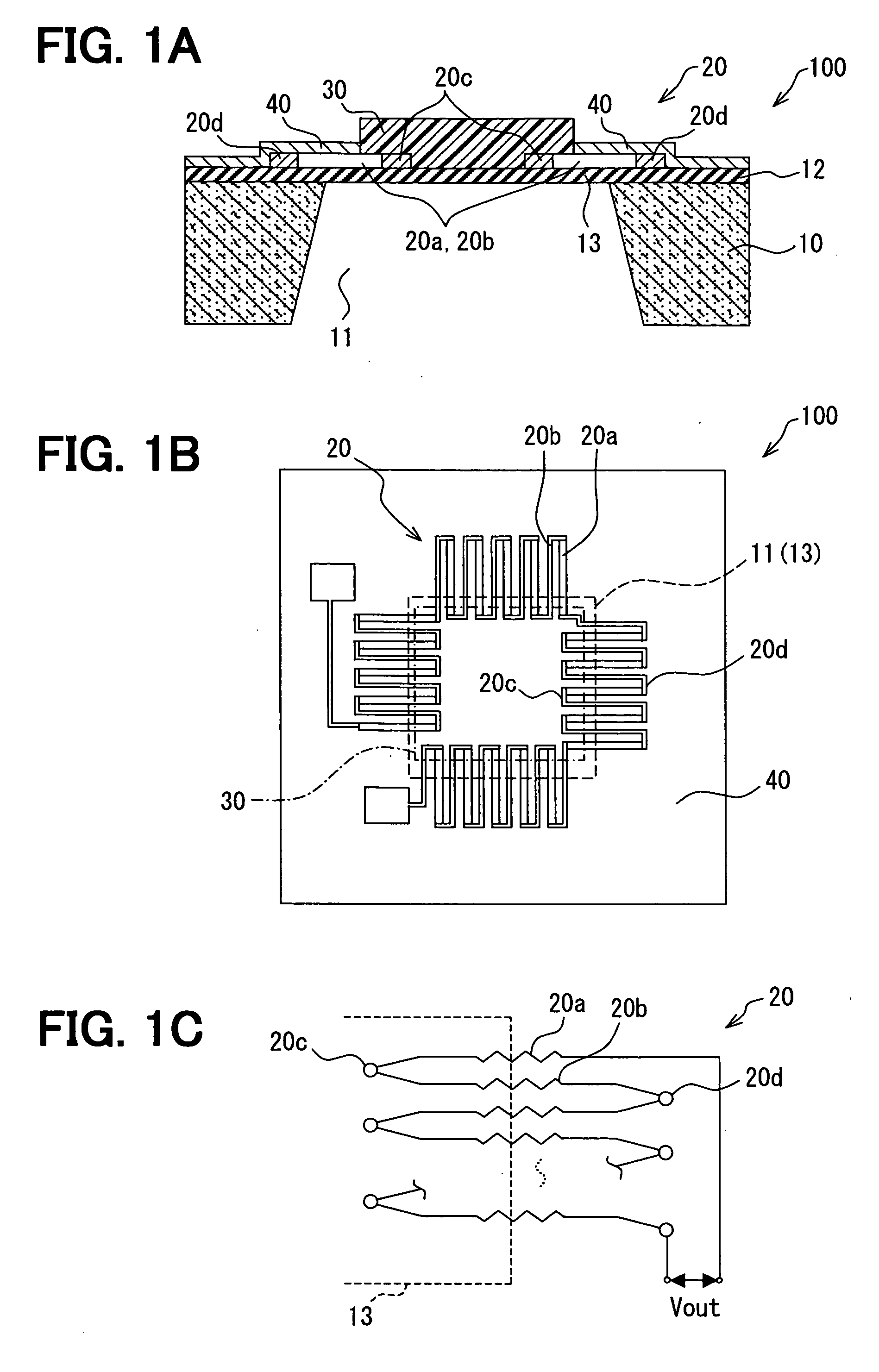
[0019]FIGS. 1A, 1B and 1C show schematically the construction of a thermopile-type infrared sensor 100 according to a first embodiment. As shown in FIG. 1A, the infrared sensor 100 mainly includes a substrate 10, a sensing element 20, an infrared light absorption film 30, and an infrared light reflection coating 40. The substrate 10 is a semiconductor substrate formed of, for example, silicon, and has a cavity 11 that is formed by wet etching from the rear surface of the substrate 10. In this embodiment, the cavity 11 opens at the rear surface to have a certain rectangular area, and the area of the opening is tapered, as shown, toward the upper surface side of the substrate 10. The rectangular opening at the upper surface of the substrate 10 is indicated by a dashed broken line in FIG. 1B and corresponds to a formation area of a membrane 13 as a thin part. The region surrounding the rectangular area indicated by the dashed broken line in FIG. 1B is a thick part where bonding pads an...

second embodiment

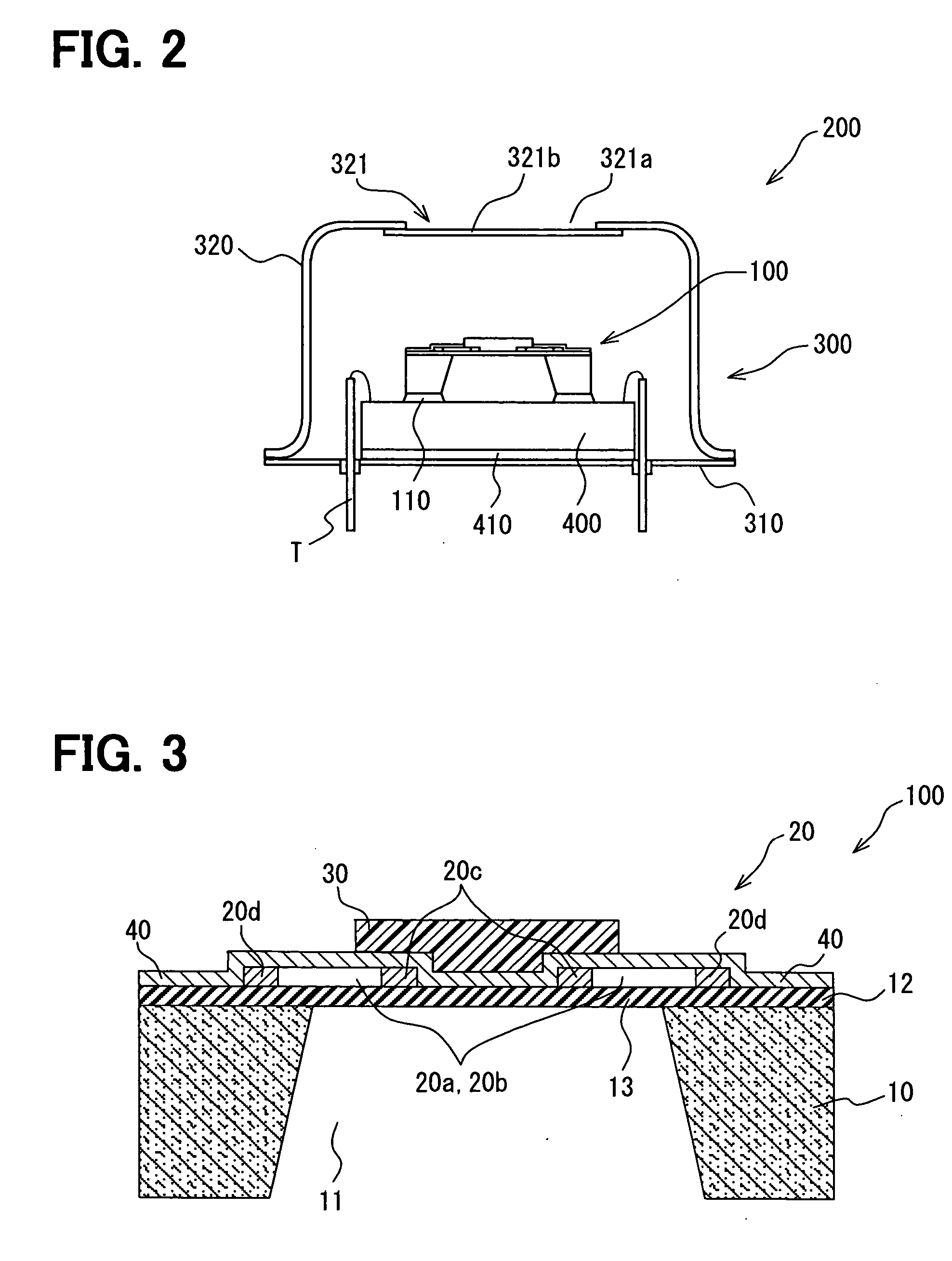
[0038]FIG. 3 shows the schematic construction of a thermopile-type infrared sensor 100 according to the second embodiment. The infrared sensor 100 according to the second embodiment has many parts common to the infrared sensor of the first embodiment. Therefore, the same reference numerals are given to corresponding or similar parts, and a detailed description of the common parts is omitted from the following description, and different parts will be mainly described.

[0039] In the first embodiment, the infrared light reflection coating 40 is located only at the region surrounding the infrared light absorption film 30. However, in this (second) embodiment, an infrared light reflection coating 40 is located not only at the surrounding region but also a region underlying an infrared light absorption film 30. That is, the infrared light reflection coating 40 covers entirely the upper surface of the substrate 10 and thereby covers the entire thermopile pattern, including hot junctions 20...

third embodiment

[0041]FIG. 5 shows the schematic construction of a thermopile-type infrared sensor 100 according to the third embodiment. The infrared sensor 100 according to the second embodiment has many parts common to the infrared sensor of the first and second embodiments. Therefore, the same reference numerals are given to corresponding or similar parts, and a detailed description of the common parts is omitted from the following description, and different parts will be mainly described.

[0042] In the second embodiment, the infrared light reflection coating 40 entirely covers the sensing element 20 with a single layer structure. However, in this (third) embodiment, an infrared light reflection coating 40 has an overlying part and an underlying part as shown in FIG. 5. That is, the overlying part of the infrared light reflection coating 40 surrounds the infrared light absorption film 30 and is laid over the cold junctions 20d like the first embodiment. The underlying part of the infrared light...


PUM


Abstract

An infrared sensor includes a substrate having a cavity, a membrane bridging the cavity, a thermopile-type infrared light sensing element, an infrared light absorption film located over the membrane in correspondence with positions of hot junctions of the thermopile, and an infrared light reflection coating located over the substrate to shield an area not covered by the infrared light absorption film. The coverage of the infrared light reflection coating is sufficient to shield an area not covered by the infrared light absorption film to improve the detection sensitivity of the sensor.

Description

CROSS REFERENCE TO RELATED APPLICATION [0001] This application is based upon, claims the benefit of priority of, and incorporates by reference the contents of Japanese Patent Application No. 2005-025397 filed on Feb. 1, 2005. FIELD OF THE INVENTION [0002] The present invention relates to an infrared sensor. The infrared sensor may employ a thermopile sensing element, a bolometric sensing element, a pyroelectric sensing element or any other infrared sensing element that outputs a signal corresponding to the infrared light received. BACKGROUND OF THE INVENTION [0003] For example, JP-A-H06-137943 discloses an infrared sensor that employs a thermopile sensing element. The thermopile sensing element includes a plurality of thermocouples connected in series and detects incident infrared light, using the Seebeck effect, in which a thermoelectromotive potential is induced between cold junctions and hot junctions of the thermocouples. [0004] The infrared sensor disclosed in the above publica...

Claims


Application Information

Patent Timeline
Patent Type & Authority Applications(United States)
IPC IPC(8): G01J5/00
CPCG01J5/12
Inventor WATANABE, KAZUAKI
Owner DENSO CORP
Why Eureka
Try Eureka