Vehicle front body structure

Inactive Publication Date: 2006-08-03
HONDA MOTOR CO LTD
View PDF2 Cites 18 Cited by
  • Summary
  • Abstract
  • Description
  • Claims
  • Application Information

AI Technical Summary

Benefits of technology

[0005] It is, therefore, an object of the present invention to provide a vehicle front body structure including a front side frame having a wheel relief portion which is sufficientl

Problems solved by technology

The wheel relief portion has a cross-sectional area much smaller than the remaining

Method used


Image

  • Vehicle front body structure
  • Vehicle front body structure
  • Vehicle front body structure

Examples


Embodiment Construction

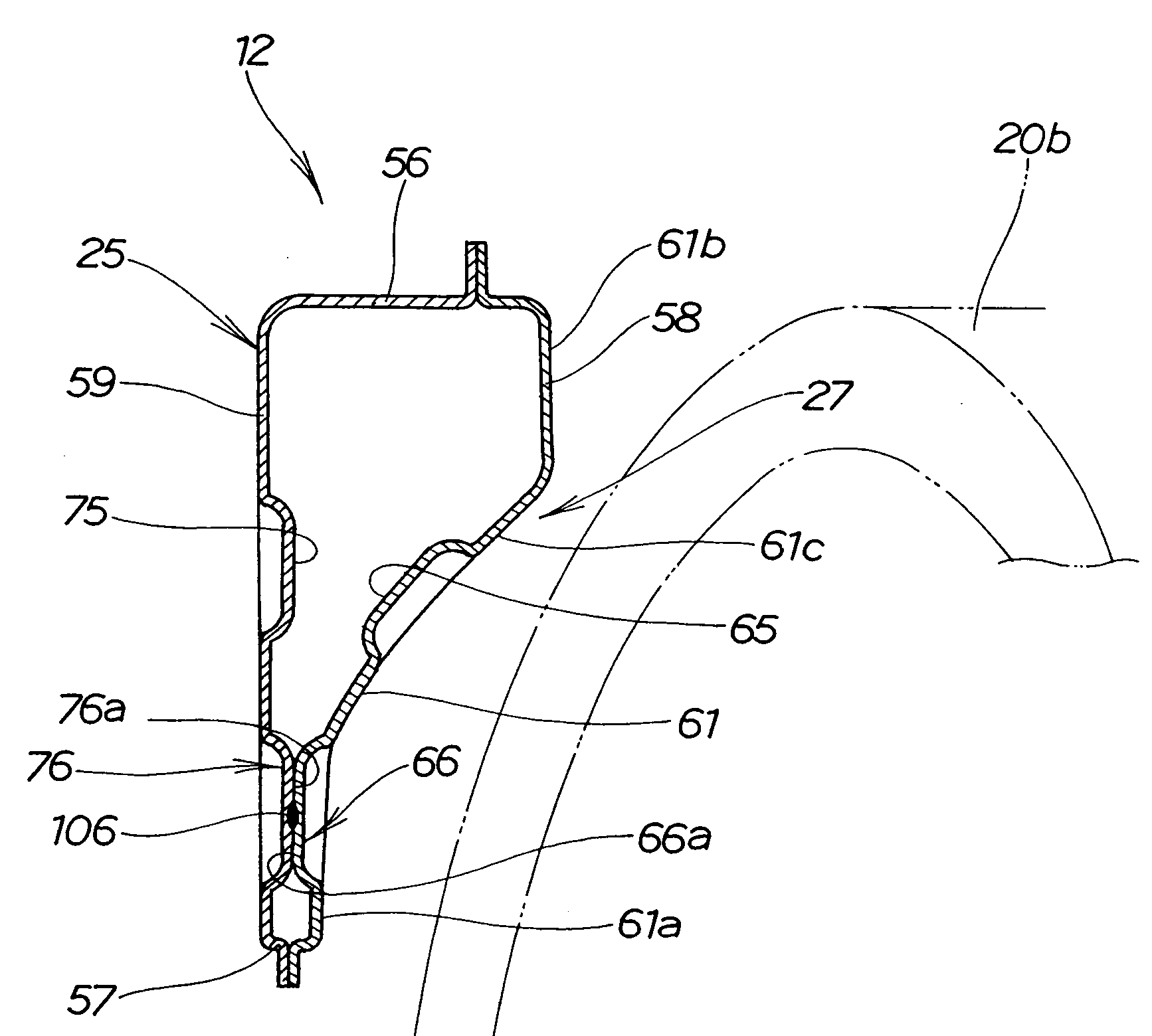
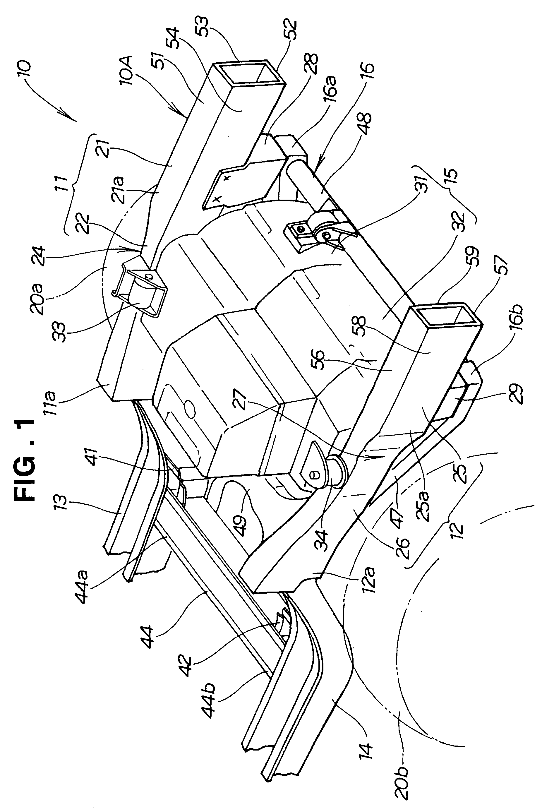
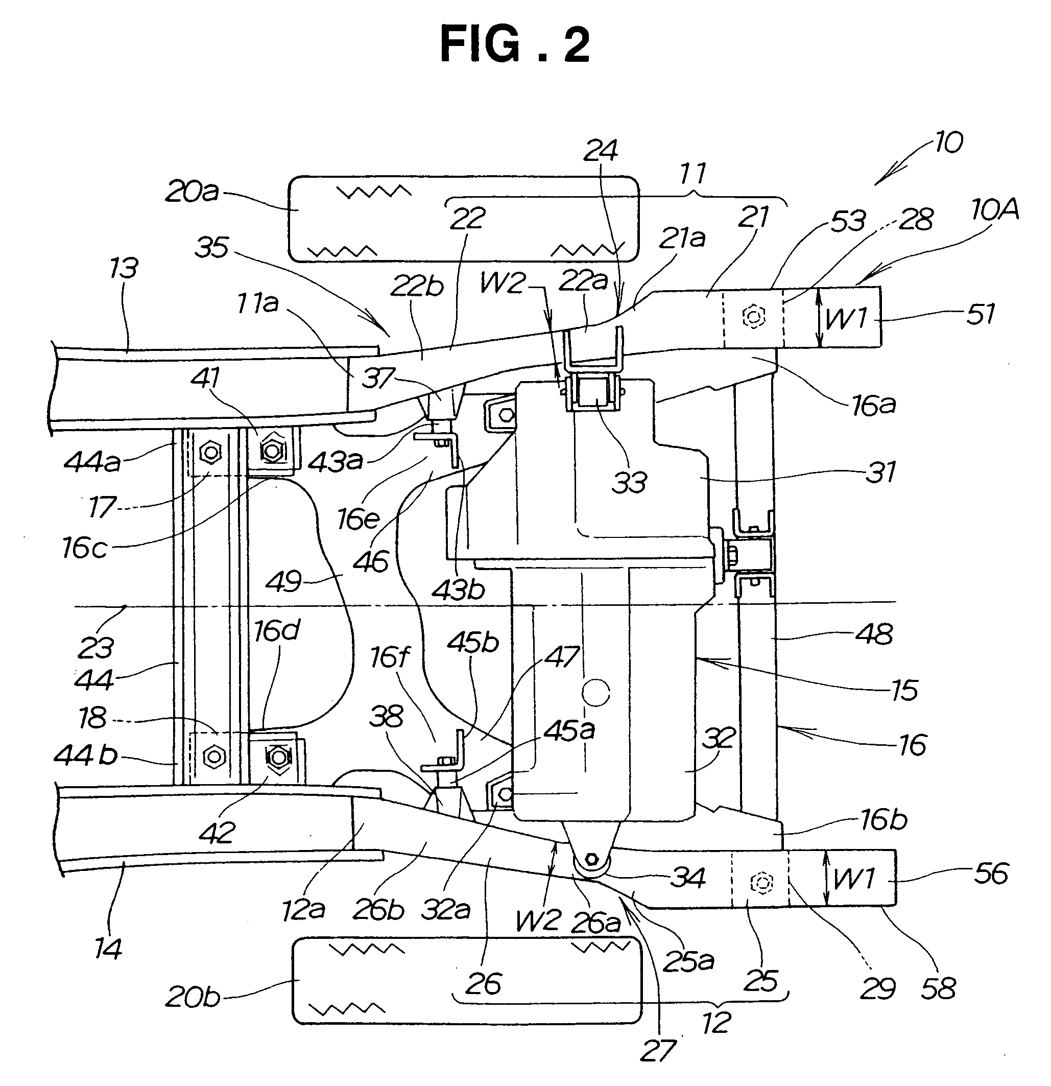
[0023] Referring now to the drawings and FIGS. 1 and 2 in particular, there is shown a vehicle front body structure 10 according to one preferred embodiment of the present invention. The vehicle body structure 10 is comprised of a front body frame 10A including a pair of laterally spaced front side frames 11 and 12 extending in a longitudinal direction of the vehicle, a pair of laterally spaced floor frames 13 and 14 extending from respective rear ends 11a, 12a of the front side frames 11, 12 in a rearward direction of the vehicle, and a front sub-frame 16 mounted to undersides of the front side frames 11, 12. A combined engine and transmission unit 15 is disposed transversely between the front side frames 11 and 12 and mounted to the front side frames 11, 12 and the front sub-frame 16.

[0024] The left front side frame 11 (shown on the right-hand side in FIG. 1 and on the upper side in FIG. 2) extends in a horizontal plane and includes a front part 21 extending rearwards from a fron...


PUM


Abstract

A vehicle front body structure includes a hollow front side frame of closed cross-sectional structure having a wheel relief portion having a horizontal width reducing to allow swivel movement of a front wheel of the vehicle. The wheel relief portion has a pair of reinforcement beads extending in a longitudinal direction of the vehicle and projecting from an outer sidewall and an inner sidewall, respectively, of the front side frame into an internal space of the hollow front side frame. The reinforcement beads have top surfaces being in abutment with each other and firmly fixed together.

Description

FIELD OF THE INVENTION [0001] The present invention relates to a vehicle front body structure including a front side frame having a wheel relief portion for allowing swivel movement of a front wheel of the vehicle. BACKGROUND OF THE INVENTION [0002] Vehicle front body structures generally include a pair of laterally spaced front side frames extending in a longitudinal direction of the vehicle, and right and left front wheels disposed on lateral outer sides of the respective front side frames. A particular example of such vehicle front body structures is disclosed in Japanese Patent Laid-Open Publication (JP-A) No. 8-108865. [0003] The disclosed vehicle front body structure, as shown in FIG. 9A hereof, includes left and right front side frames 201 (only left one being shown) extending in a longitudinal direction of the vehicle with a combined engine-and-transmission unit 205 disposed between the left and right front side frames 201. Left and right front wheels 206 (only left one bein...

Claims


Application Information

Patent Timeline
IPC IPC(8): B62D21/00B60P3/22
CPCB60T17/046B62D25/16B62D21/152B62D21/02
Inventor MITSUI, JUNYASUHARA, SHIGETOYASUI, KEN
Owner HONDA MOTOR CO LTD
Why Eureka
Try Eureka