Smart entry system for vehicle

a technology for entering systems and vehicles, applied in anti-theft devices, roofs, instruments, etc., can solve problems such as security problems and give passengers troubl

Inactive Publication Date: 2006-08-03
MAZDA MOTOR CORP
View PDF12 Cites 43 Cited by
  • Summary
  • Abstract
  • Description
  • Claims
  • Application Information

AI Technical Summary

Benefits of technology

[0010] Accordingly, when the passenger wants to open the closed door, the door can be easily unlatched just by operating the request switch from the outside of vehicle, without applying a large operation force to the door handle to unlatch the door. Meanwhile, when the passenger wants to close the door from its open state, the door can be latched whether the request switch is operated or not or the verification with the ID signal is confirmed or not. Thus, the latch / unlatch of the door can be done easily and promptly, so the operation of the door is improved. Also, the door can be latched surely, so the security is improved.
[0038] Accordingly, since the specified door is unlatched basically only when the portable device is located outside the vehicle, the portable device can be prevented properly from being locked up in the vehicle cabin. Also, when the door is the half-latched state, the door is unlatched at least with conditions of the detection that the portable device is located outside the vehicle. Thereby, the door can be closed again by being unlatched from its half-latched state. Also, since the door is unlatched upon verification with the ID signal even when the door is the half-latched state, the proper security can be provided as well.

Problems solved by technology

This would give the passenger some trouble.
Also, if the passenger fails the operation to latch the door after closing the door because of this some trouble, this would bring a security problem.

Method used


Image

  • Smart entry system for vehicle
  • Smart entry system for vehicle
  • Smart entry system for vehicle

Examples


Embodiment Construction

[0065] Hereinafter, preferred embodiments will be described referring to the accompanied drawings.

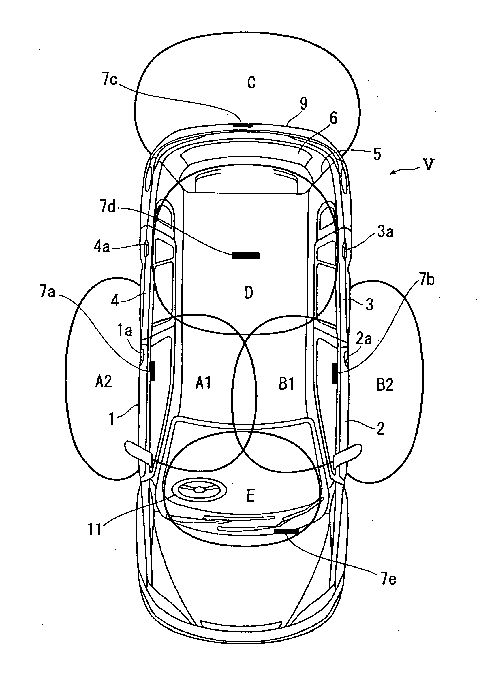
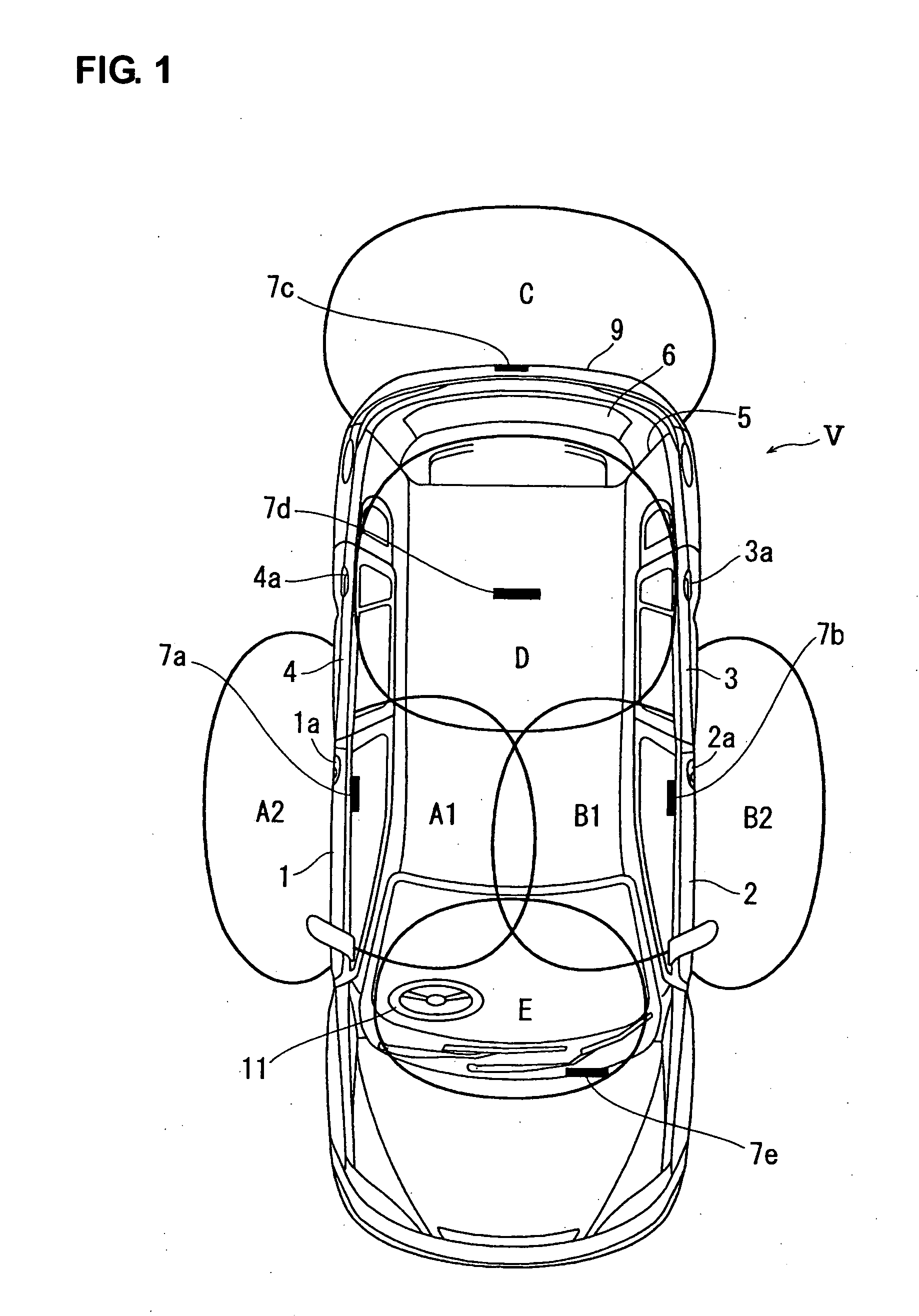
[0066] In FIG. 1, a vehicle V includes side doors comprising a driver-seat door 1, an assistant-seat door 2 and a pair of rear-seat doors 3, 4. These doors 1 through 4 are a rear-side opening type of door. Respective door handles of the doors 1 through 4 are denoted by reference characters 1a through 4a. At the door handles 1a, 2a are provided request switches 1b, 2b for locking / unlocking the doors using ID signals which will be described below (see FIGS. 6 and 7). Herein, the request switch may be tuned ON by a slightly-pushing operation.

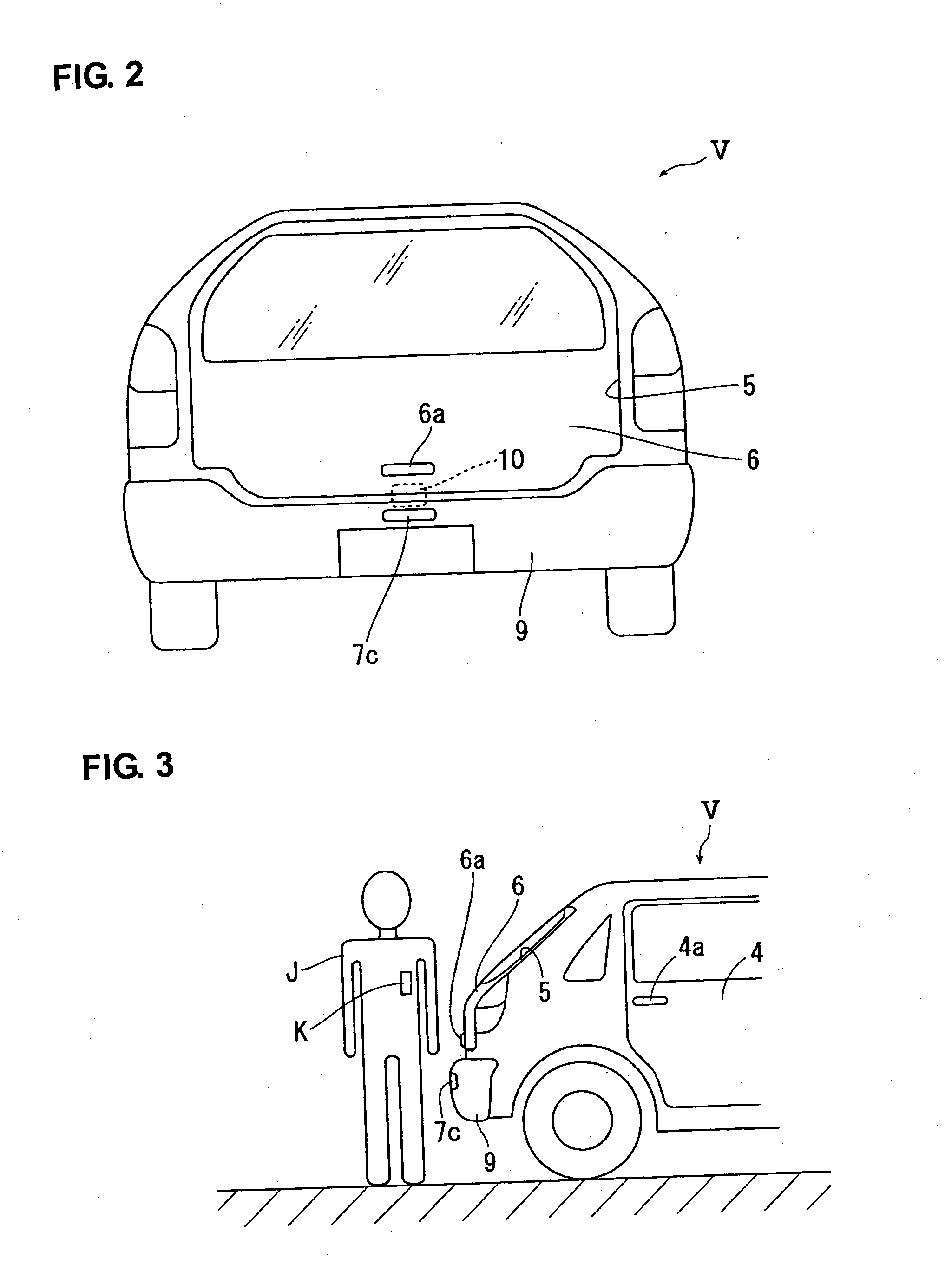
[0067] As shown in FIGS. 2 through 5, the vehicle V has a rear opening 5 formed at the vehicle rear, which is closed and opened by a lift gate 6 as a back door. The lift gate 6 is a lower-side opening type of door in the present embodiment. Its closed state is shown in FIG. 3, its opened state is shown in FIG. 4, and its slightly opened state is show...


PUM


Abstract

The specified door other than the driver-seat door is lathed or unlatched by the electromagnetic latch mechanism. When the request switch of the door in the closed state is operated, the request signal is transmitted from the antenna of the onboard transmitter. The ID signal is transmitted by the portable device responsive to the request signal, and the ID signal is received by the antenna of the onboard receiver. Herein, the door is unlatched by the electromagnetic latch mechanism upon verification with the ID signal received. When the door in the open state is closed, the electromagnetic latch mechanism is operated to latch the door whether the request switch is operated or not or the verification with the ID signal is executed. Accordingly, the superior smart entry system for a vehicle without security problems can be provided.

Description

BACKGROUND OF THE INVENTION [0001] The present invention relates to a smart entry system for a vehicle. [0002] A so-called smart entry system (or called a smart key system) has been recently used for vehicles, especially, automotive vehicles, in which a door is locked and unlocked upon verification with ID signal transmitted by a portable device held by a passenger, for example, as disclosed in Japanese Patent Application Laid-Open No. 2003-269019. This system comprises the onboard transmitter (placed on the vehicle) to transmit the request signal, the onboard receiver (placed on the vehicle) to receive the ID signal, and the portable device to be held by the passenger, which comprises the receiver to receive the request signal and the transmitter to transmit the ID signal. When the request switch provided at the door handle is operated, for example, the request signal is transmitted by the onboard transmitter, the portable device receives the request signal and transmits the ID sig...

Claims


Application Information

Patent Timeline
Patent Type & Authority Applications(United States)
IPC IPC(8): B60T7/16B60J5/00B60R25/20B60R25/24
CPCB60R25/2036B60R25/246G07C9/00309G07C2209/64G07C2209/65
Inventor YAMASHITA, TAKEHARU
Owner MAZDA MOTOR CORP
Why Eureka
Try Eureka