

System for detecting an RFID tag
- Summary
- Abstract
- Description
- Claims
- Application Information
AI Technical Summary
Benefits of technology
Problems solved by technology
Method used
Image

Examples
Embodiment Construction
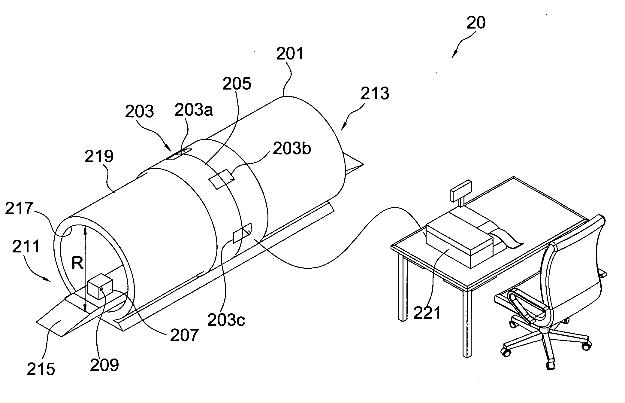
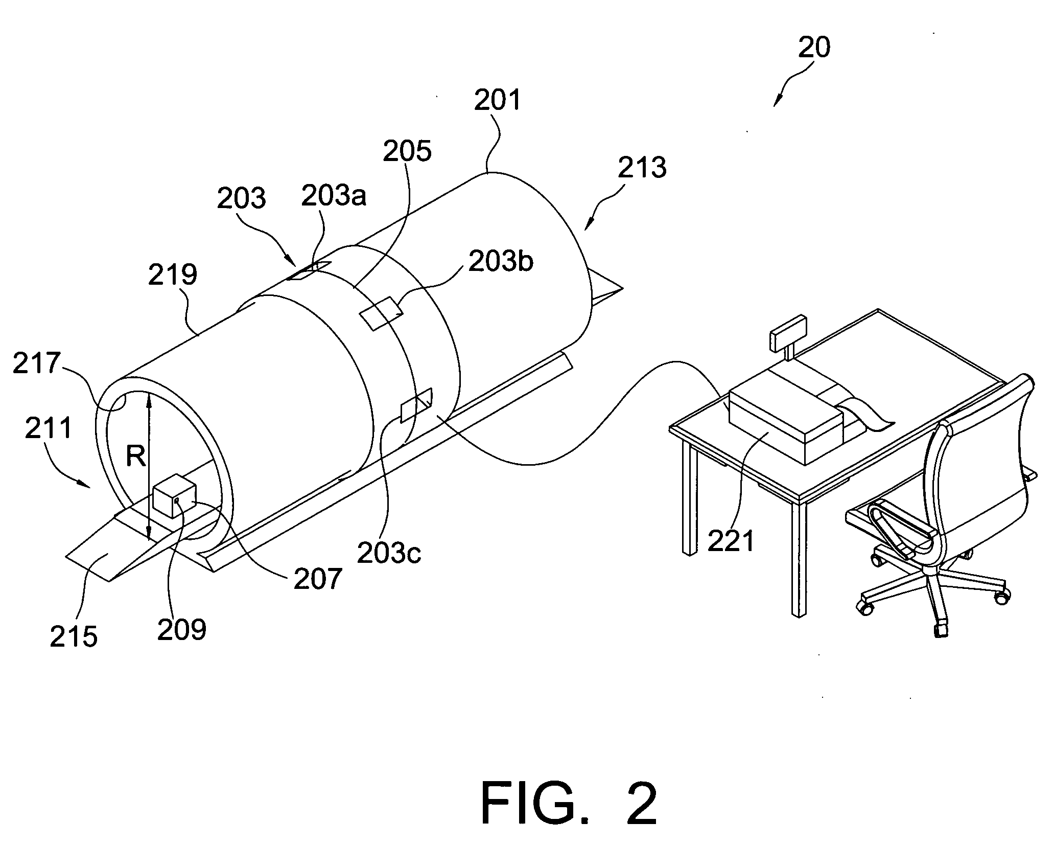
[0013] Referring to FIG. 2, a system 20 is suitable for use in a supermarket or department store to balance purchases. The system 20 includes a tunnel 201 and an antenna array 203.
[0014] The tunnel 201, having a characteristic linear dimension R of a characteristic cross-section 205, is suitable for an object 207 to pass through. In this embodiment, the characteristic cross-section 205 is a circular area and the characteristic linear dimension R is the diameter of the circular area. The antenna array 203, arranged along a perimeter of the characteristic cross-section 205, is for detecting, at an operating frequency, a radio frequency identification tag 209 on the object 207 when the object 207 passes through the tunnel 201. Although the characteristic cross-section 205 of the first embodiment is a circular area, the present invention does not limit its shape. For example, a rectangle may also work.
[0015] The electromagnetic waves generated by the antenna array 203 attenuate expone...
PUM
 Abstract
Description
Claims
Application Information