
Enhanced video metrology tool
a video metrology and tool technology, applied in the field of machine vision inspection systems, can solve the problems of limited features and graphical user interface controls of video tools, particularly dimensional metrology video tools, and the resulting video tool parameters are set, so as to achieve a high level of control over the creation of tool parameters and the precise way to create tools
Patent Information
- Authority / Receiving Office
- US · United States
- Patent Type
- Applications(United States)
- Current Assignee / Owner
- Publication Date
- 2006-08-03
Smart Images
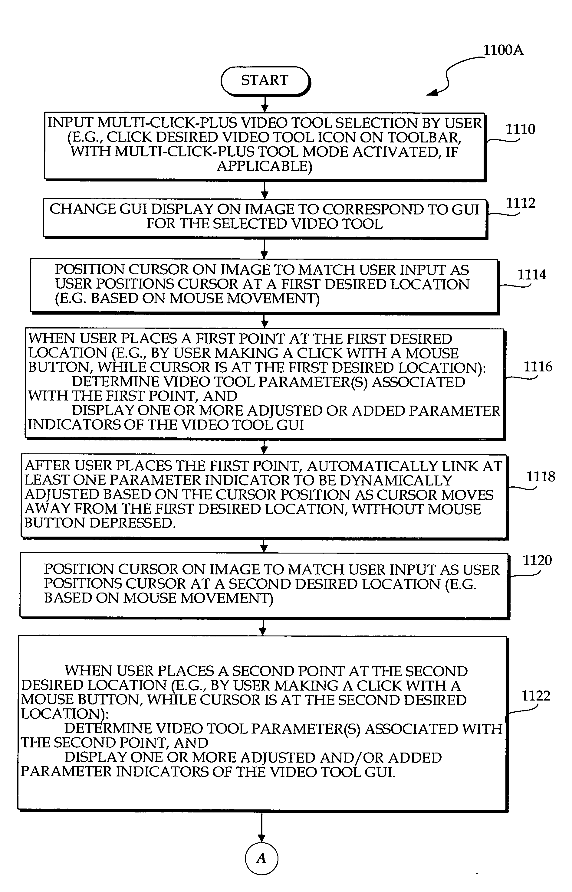
Figure 1 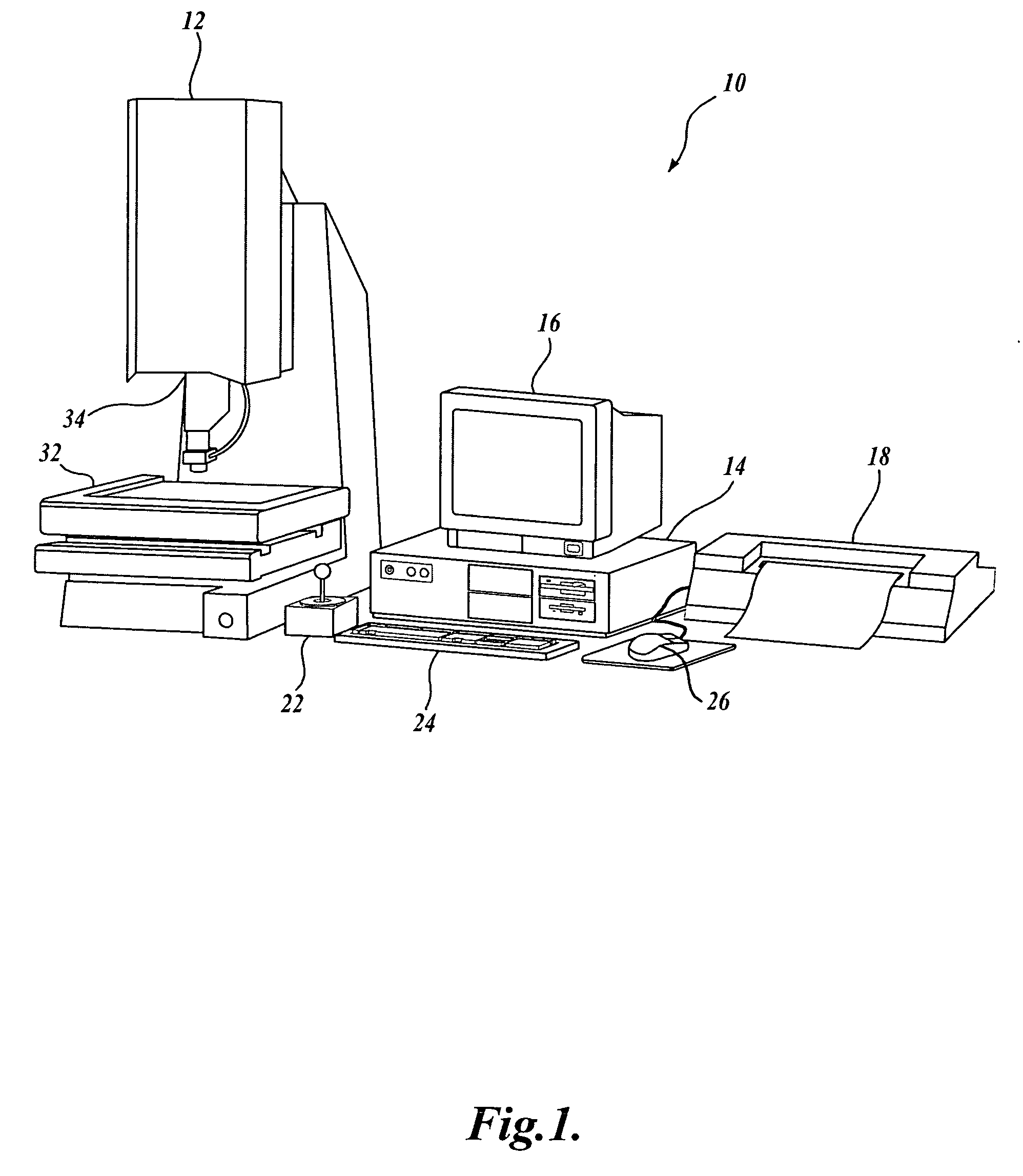
Figure 2 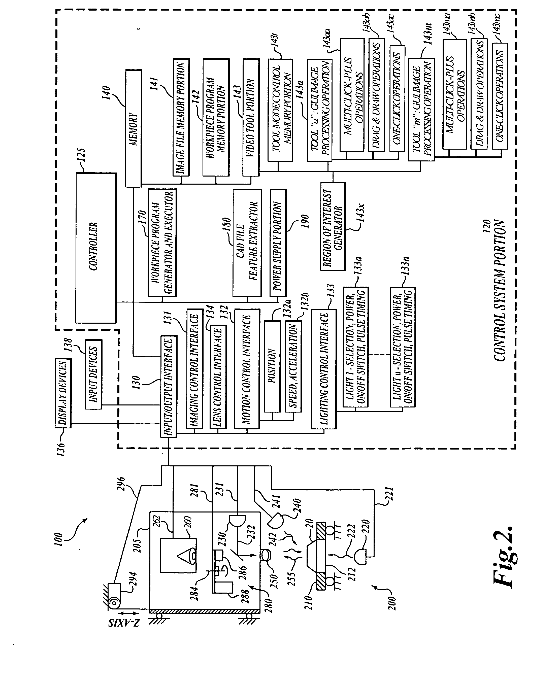
Figure 3
Abstract
Description
CROSS-REFERENCE TO RELATED APPLICATION
[0001] This application claims the benefit of U.S. Provisional Application No. 60 / 648,956, filed Jan. 31, 2005, under the provisions of 35 U.S.C. § 119.FIELD OF THE INVENTION
[0002] The invention relates generally to machine vision inspection systems, and more particularly to video metrology tools usable to define inspection operations for such systems. BACKGROUND OF THE INVENTION
[0003] Precision machine vision inspection systems (or “vision systems” for short) can be utilized to obtain precise dimensional measurements of inspected objects and to inspect various other object characteristics. Such systems may include a computer, a camera and optical system, and a precision stage that is movable in multiple directions so as to allow the camera to scan the features of a workpiece that is being inspected. One exemplary prior art system that is commercially available is the QUICK VISION® series of PC-based vision systems and QVPAK® software availab...
Examples
Embodiment Construction
[0024]FIG. 1 is a block diagram of one exemplary machine vision inspection system 10 usable in accordance with the present invention. The machine vision inspection system 10 includes a vision measuring machine 12 that is operably connected to exchange data and control signals with a controlling computer system 14. The controlling computer system 14 is further operably connected to exchange data and control signals with a monitor or display 16, a printer 18, a joystick 22, a keyboard 24, and a mouse 26. The monitor or display 16 may display a user interface suitable for controlling and / or programming the operations of the machine vision inspection system 10.
[0025] The vision measuring machine 12 includes a moveable workpiece stage 32 and an optical imaging system 34 which may include a zoom lens or interchangeable lenses. The zoom lens or interchangeable lenses generally provide various magnifications for the images provided by the optical imaging system 34. The machine vision inspe...