Indexed optical fiber connector

a technology of optical fiber connectors and optical fibers, applied in the field of indexed optical fiber connectors, can solve the problems of not being able to determine the exact positional relationship, and none of the available connector systems identified can be completely disassembled and retained, so as to improve precision, reduce manufacturing costs, and improve the effect of precision

Active Publication Date: 2006-08-03
MOLEX INC
View PDF12 Cites 27 Cited by
  • Summary
  • Abstract
  • Description
  • Claims
  • Application Information

AI Technical Summary

Benefits of technology

[0017] If one could view the end portion of a “lit” optical fiber what would be seen is a circle with a dot of light somewhat displaced from the exact center of the circle. Eccentricity can be understood as a two-dimensional vector having magnitude and direction components. The “magnitude component” of the eccentricity vector is the straight line distance between the center of the circle and the dot of light, while the “direction component” of the eccentricity vector is the angle made by that straight line with respect to the X-axis of a 2-dimensional Cartesian coordinate system whose origin is at the center of the circle. It is noted that ferrules used in conventional optical connectors (i.e., ST, SC and FC) have a 2.5 mm diameter while the ferrule used in a preferred embodiment of the present invention has a diameter which is half that size as utilized by the LC connection system. With the use the reduced-size ferrule, the magnitude component of the eccentricity vector is proportionally reduced—which improves precision.
[0018] Rotating one of two interconnected ferrules typically changes the relative position of the fibers held within the passageway because of the eccentricity of the optical fiber core with respect to the ferrule. Because it is very difficult to control the eccentricity of the optical fiber core in the ferrule in which it is terminated, it is difficult to achieve desired losses of 0.1 dB or less in single mode fibers without maintaining close tolerances so that the opposed cores are aligned to within about 0.7 microns. This, of course, increases the manufacturing cost. If the total eccentricities of the two optical fiber ends to be joined are identical, or at least very nearly so, then a low-loss connection can be achieved by merely rotating, within the alignment sleeve, one ferrule with respect to the other, until maximum coupling is observed (minimum insertion loss).

Problems solved by technology

Further, none of the available connector systems identified can be entirely disassembled and retain the fiber eccentricity compensation if they have such.
Once removed it is not possible to determine the exact positional relationship between the fiber holding structure and the connector body.

Method used


Image

  • Indexed optical fiber connector
  • Indexed optical fiber connector
  • Indexed optical fiber connector

Examples


Embodiment Construction

[0025] The organization and manner of the structure and operation of the invention, together with further objects and advantages thereof, may best be understood by reference to the following description taken in connection with the accompanying drawings wherein like reference numerals identify like elements in which:

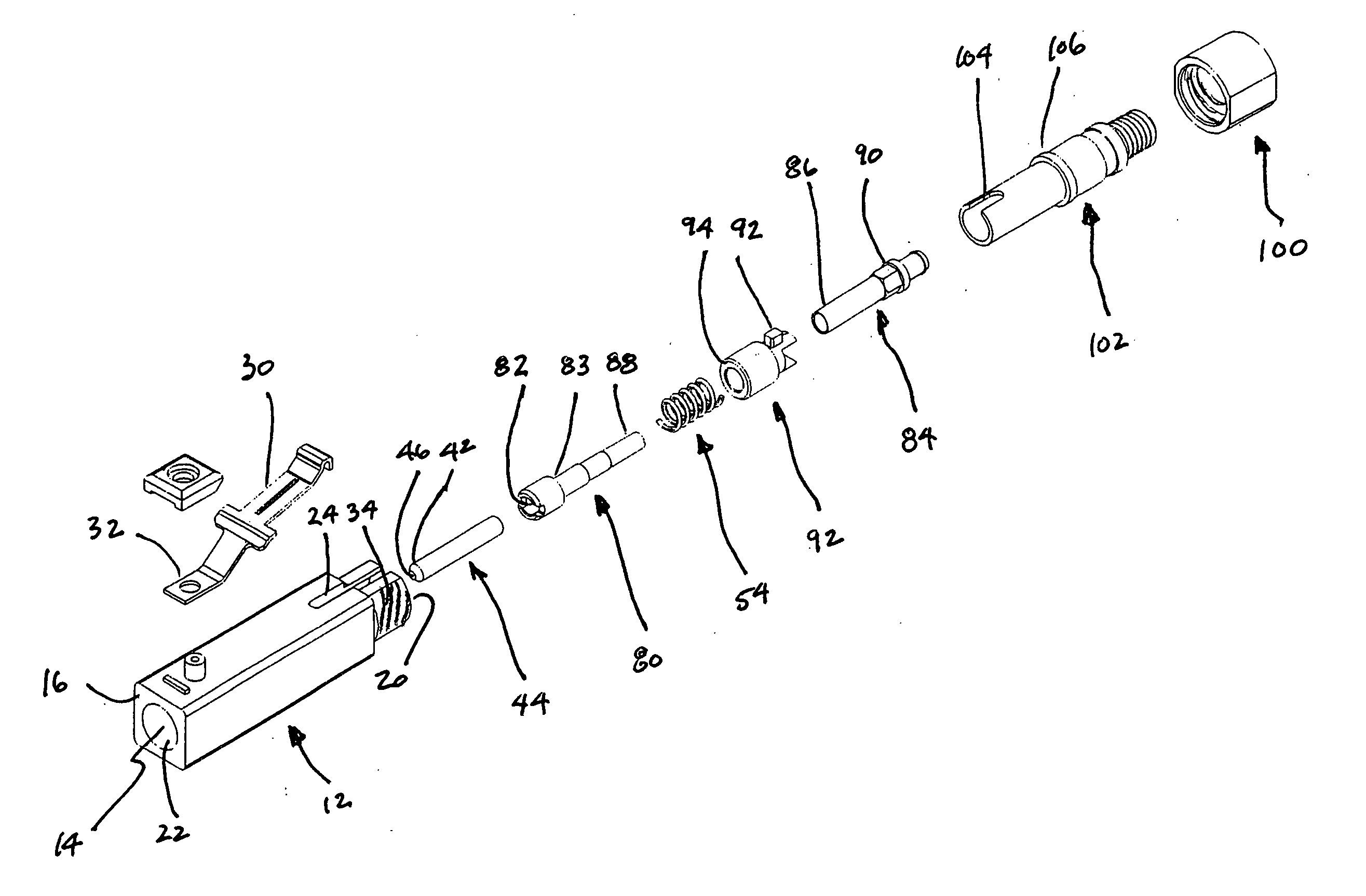
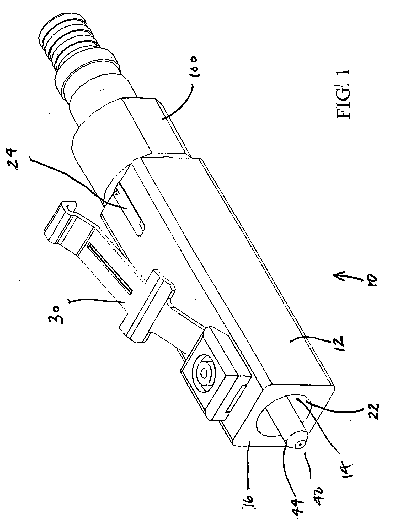
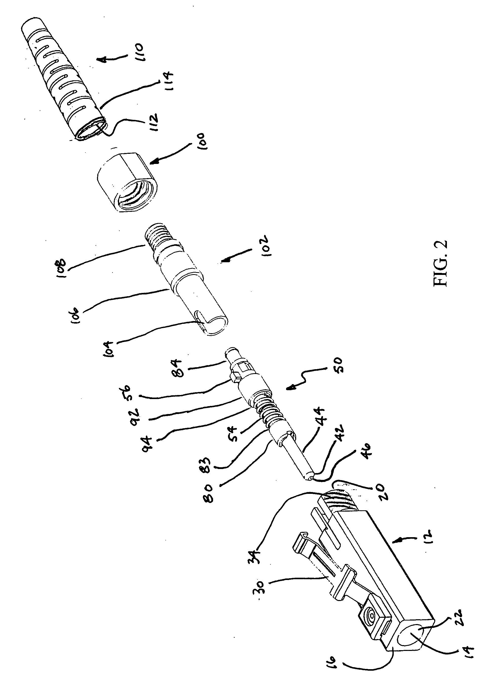
[0026] The present invention enables fiber eccentricity to be compensated through the use of an indexing feature or portion 90 in the fiber holder structure 50. The fiber holder is designed such that the ferrule 44 can be configured with one of six (hex) rotational positions relative to the indexing portion 90 although more or fewer rotational positions may be used. Such a design enables the ferrule 44 and the fiber holder 50 to be installed in connector body with an index in one of six rotational positions (0 degrees, 60 degrees, 120 degrees, 180 degrees, 240 degrees, and 300 degrees). The particular position selected is determined during fabrication of the connector b...


PUM


Abstract

A high-performance connector for optical fibers includes a cylindrical ceramic or metallic ferrule installed in a structure. This structure is positioned in a non-plastic (metallic system) base member to form a fiber holder. This overall generally cylindrical structure includes a small passageway along its central axis for holding an optical fiber. This entire structure is mounted within the non-plastic housing that includes an opening at one end thereof from which the ceramic ferrule protrudes. A cylindrical spring that is integral to the ferrule support structure and interacts with an interior surface of the surrounding structure via a secondary piece of the cylindrical structure urges the ceramic ferrule outward from the opening in the housing. The housing includes a metallic leaf-spring latch which is located on a single surface thereof, which is manually operable and used to lock the connector to an associated receptacle. Said connector; because it is manufactured of non-plastics in its structural elements (metallics and/or ceramics) has very stable optical performance criteria over a broad range of environments (both thermal and mechanical). The high performance optical connector also introduces the ability to remove the cylindrical fiber holder to directly inspect or clean the sensitive internal components (springs, internal metallic or ceramic components). In addition, the cylindrical structure provides a mean of “tuning” it to remove the effects of fiber eccentricity. When tuned, the fiber holder retains such tuning even outside the housing allowing re-assembly of the high-performance connector without loss of “tuning”.

Description

[0001] This application claims priority from a provisional application No. 60 / 636,880 filed on Dec. 20, 2004. TECHNICAL FIELD [0002] This invention relates to apparatus for making connections between optical devices, and more particularly to a connector for terminating an optical fiber. BACKGROUND OF THE INVENTION [0003] Optical fiber connectors are an essential part of substantially any optical fiber communication system. For instance, such connectors may be used to join segments of fiber into longer lengths; to connect fiber to active devices such as transceivers, detectors and repeaters; or to connect fiber to passive devices such as switches and attenuators. The central function of an optical fiber connector is the maintenance of two optical fiber ends such that the core of one of the fibers is axially aligned with the core of the other fiber; and consequently, all of the light from one fiber is coupled to the other fiber as efficiently as possible. This is a particularly challe...

Claims


Application Information

Patent Timeline
Patent Type & Authority Applications(United States)
IPC IPC(8): G02B6/36
CPCG02B6/3831G02B6/3843G02B6/3851G02B6/3888G02B6/38875G02B6/38G02B6/255
Inventor DYE, DAVID E.
Owner MOLEX INC
Why Eureka
Try Eureka