
Lens unit used for camera module having optical filter therein

Inactive Publication Date: 2006-08-03
SAMSUNG ELECTRO MECHANICS CO LTD
View PDF3 Cites 6 Cited by
  • Summary
  • Abstract
  • Description
  • Claims
  • Application Information

AI Technical Summary

Benefits of technology

[0014] An object of the present invention is to provide a lens unit for a camera module having an optical filter therein, capable of minimizing quality deterioration of a product by minimizing inflow of foreign substance during a manufacturing process.
[0015] Another object of the present invention is to provide a lens unit for a camera module having an optical filter therein, that can be applied in designing and manufacturing of a digital apparatus having various structures by lowering the height of an assembly that mounts the optical filter in an image sensor unit.
[0016] A further another object of the present invention is to provide a lens unit for a camera module having an optical filter therein, capable of simplifying a manufacturing process thereof by allowing the optical filter to be easily mounted in the inside of an image sensor unit and minimizing quality deterioration of a product.

Problems solved by technology

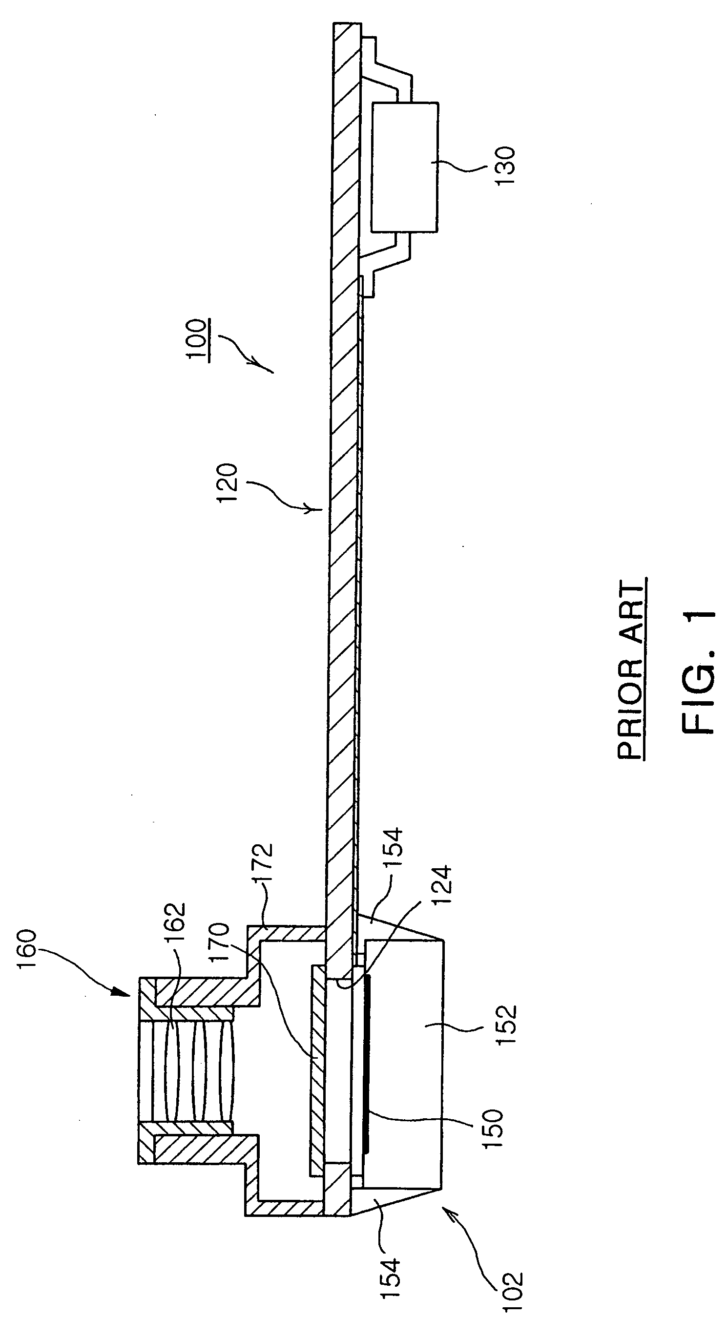
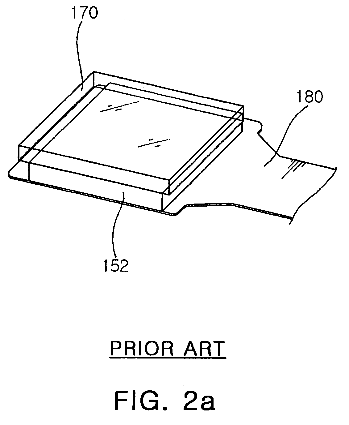
However, in the above conventional methods, when the optical filter 170 is mounted on the upper surface of the flexible substrate 120, mounted on the image sensor 152, or mounted within the housing 172 as described above, foreign substance or an adhesive attaches to or stains the optical filter 170 during a manufacturing process thereof, so that a light receiving operation of the image sensor 152 is disturbed and thus malfunction in the optical performance of the camera module 100 is generated.

Method used


Image

  • Lens unit used for camera module having optical filter therein
  • Lens unit used for camera module having optical filter therein
  • Lens unit used for camera module having optical filter therein

Examples

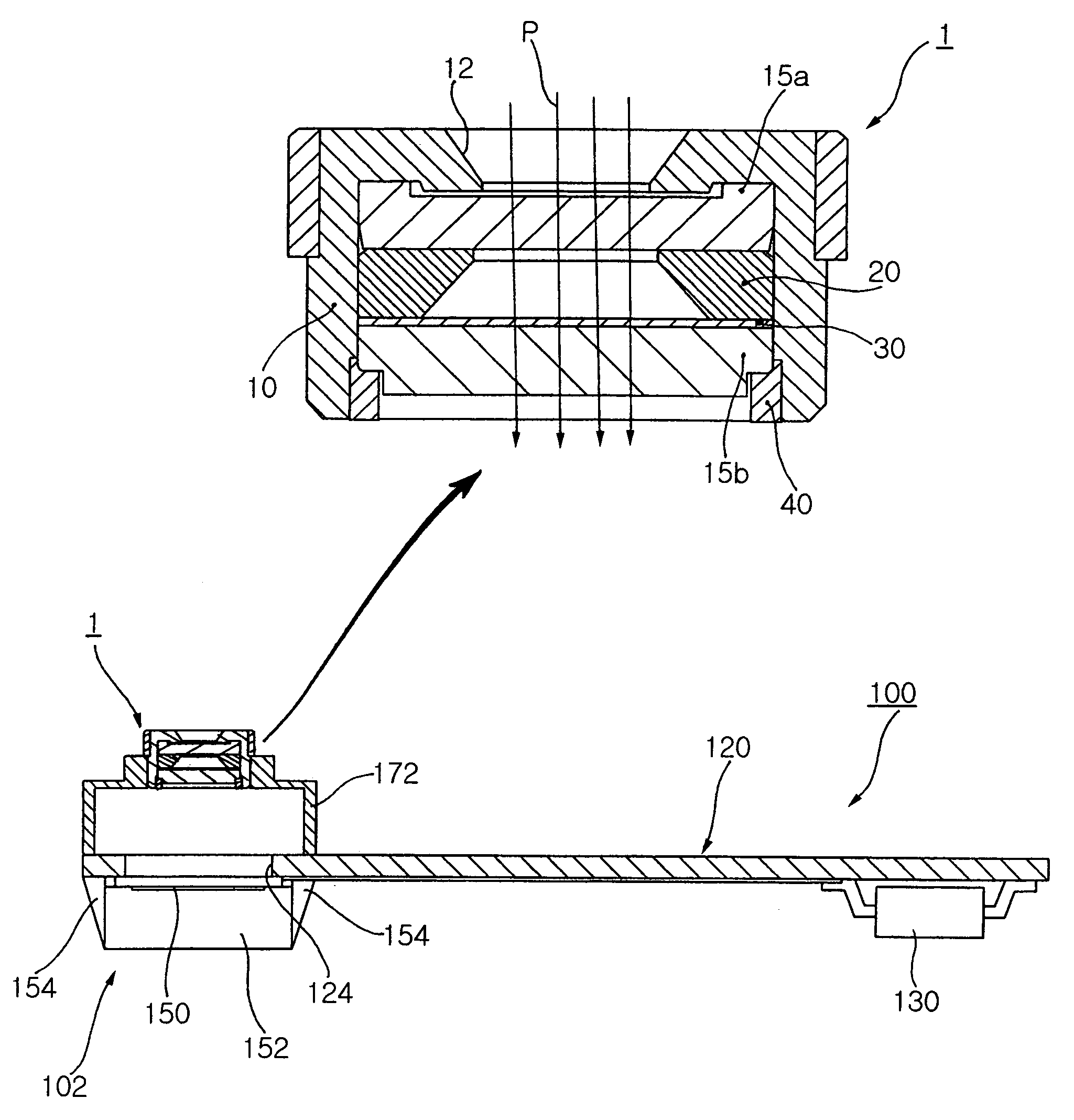

Embodiment Construction

[0028] Reference will now be made in detail to the preferred embodiments of the present invention, examples of which are illustrated in the accompanying drawings.

[0029] Referring to FIG. 3, a lens unit 1 for a camera module having an optical filter therein according to the present invention is provided to an image sensor unit 102 of a camera module 100 to transmit light to an image sensor 152.

[0030] The lens unit 1 includes a casing 10 having a cavity therein. The casing 10 has a cylindrical structure in which a light-receiving hole 12 is formed in one side.

[0031] Referring to FIG. 3, the casing 10 has an outer diameter that can be mounted in a housing 172 of the image sensor unit 102. Of course, the casing 10 does not necessarily have a cylindrical shape but can have a polygonal cross-section depending on the shape of the lens used.

[0032] The present invention has a plurality of lenses 15a and 15b aligned in the inside of the casing 10, for transmitting light that has passed th...


PUM


Abstract

A lens unit for a camera module having an optical filter therein is provided. The lens unit includes a casing, a plurality of lenses, an optical filter, and a fixing member. The casing has a light-receiving hole formed in one side thereof and has a structure in which a cavity is formed. The lenses are aligned in the inside of the casing to transmit light that passes through the light-receiving hole. The optical filter is disposed in the inside of the casing to block a partial wavelength of light and the fixing member maintains the lenses and the optical filter at an aligned state in the inside of the casing. A separate optical filter doesn't need to be mounted in the camera module but is integrally formed in the inside of the casing, so that inflow of foreign substance during the manufacturing process is minimized.

Description

RELATED APPLICATION [0001] The present application is based on, and claims priority from, Korean Application Number 2005-8223, filed Jan. 28, 2005, the disclosure of which is hereby incorporated by reference herein in its entirety. BACKGROUND OF THE INVENTION [0002] 1. Field of the Invention [0003] The present invention relates to a lens unit for a camera module used for a camera system of a digital optical apparatus, and more particularly, to a lens unit for a camera module having an optical filter therein, capable of minimizing inflow of foreign substance during a manufacturing process, minimizing the size of a camera module assembly in which an optical filter is mounted, minimizing deterioration of optical performance, and simplifying a manufacturing process by integrally forming an optical filter in the inside of a casing without separately mounting an optical filter on the camera module. [0004] 2. Description of the Related Art [0005] Currently, many cellular phone companies de...

Claims


Application Information

Patent Timeline
IPC IPC(8): G03B7/099G02B7/02G03B11/00
CPCG03B7/099H04N5/2254Y02E60/10G01B7/16G01M5/0008H01M10/465
Inventor KIM, HO KYOUMNAM, HYOUNG WOO
Owner SAMSUNG ELECTRO MECHANICS CO LTD
Learn More