Electronic device and case thereof

a technology applied in the field of electronic devices and cases, to achieve the effect of convenient assembly work and satisfactory appearan

Inactive Publication Date: 2006-08-03
SONY CORP
View PDF2 Cites 4 Cited by
  • Summary
  • Abstract
  • Description
  • Claims
  • Application Information

AI Technical Summary

Benefits of technology

[0008] According to the embodiments of the present invention, the third covering member covers the heads of screws fastening the first and the second covering member to the functional unit and lying in the side surfaces of the electronic device. Thus the heads of the screws do not need to be concealed individually by concealing caps and concealing plugs. Consequently, the electronic device has an aesthetically satisfactory appearance and facilitates assembling work.

Problems solved by technology

Attaching the concealing caps and concealing plugs to the case requires troublesome work disadvantageous for the improvement of the efficiency of assembling work for assembling the electronic device.

Method used


Image

  • Electronic device and case thereof
  • Electronic device and case thereof
  • Electronic device and case thereof

Examples


first embodiment

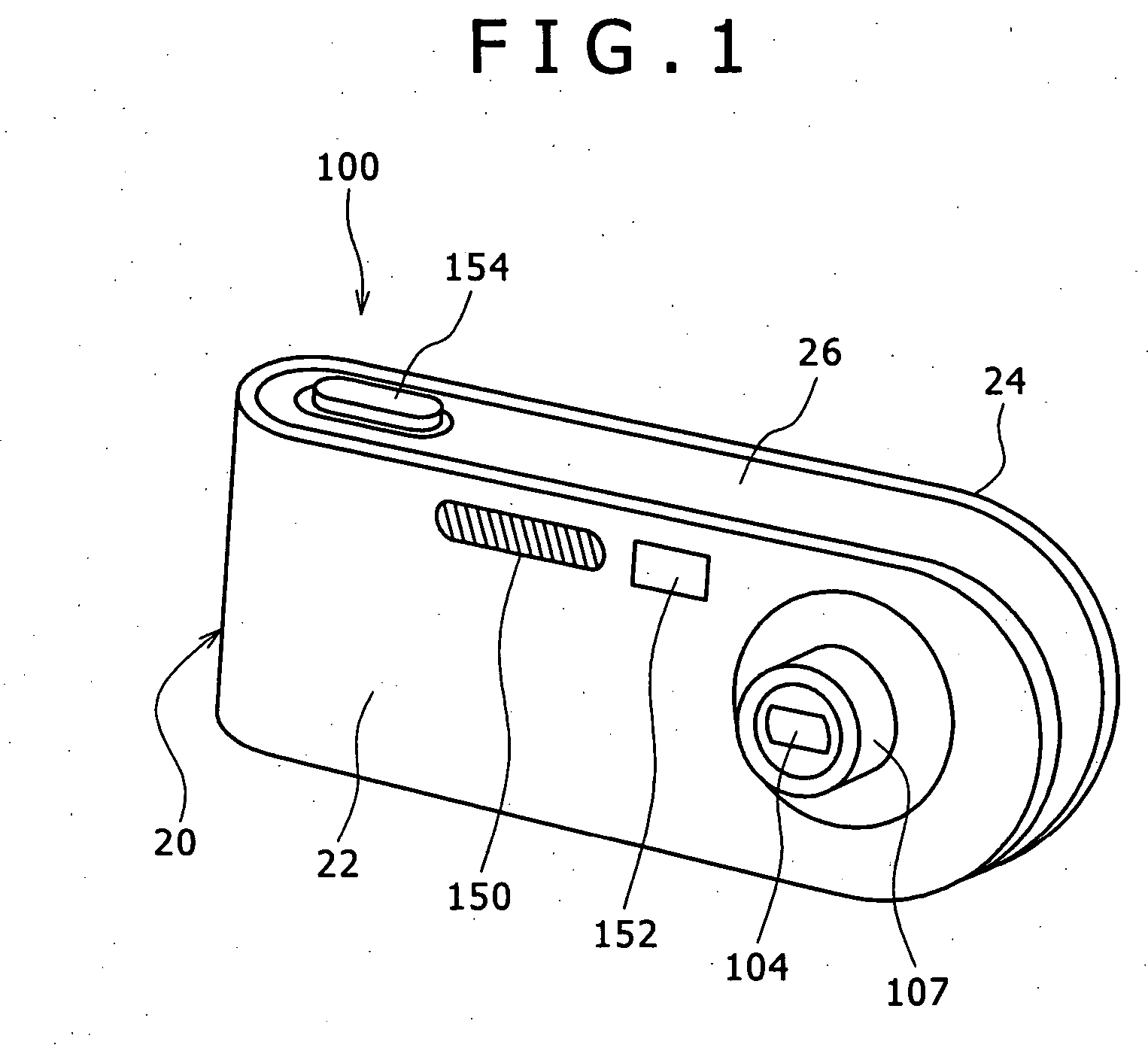
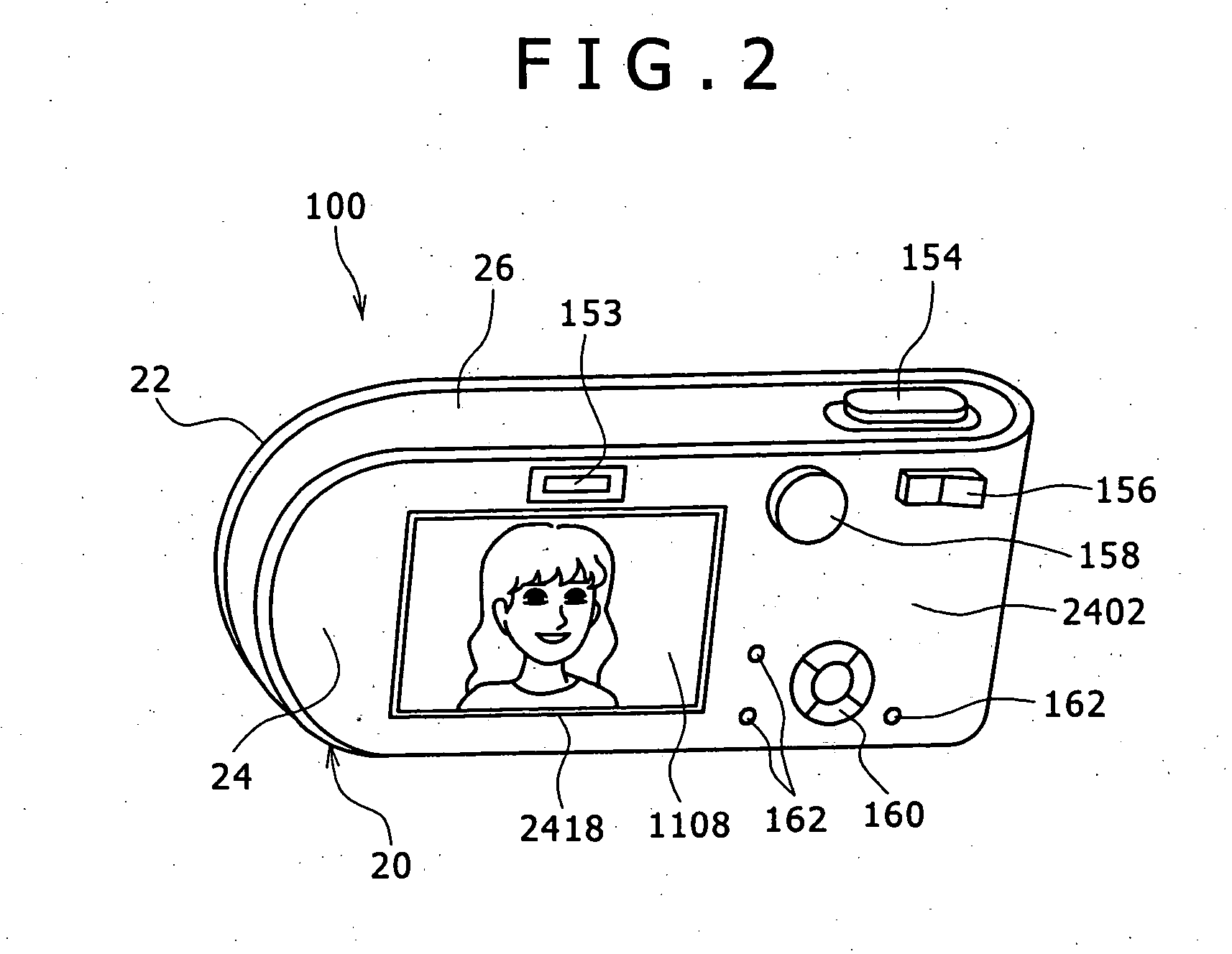
[0022]FIG. 1 is a perspective, front view of a digital still camera 100 in a first embodiment according to the present invention, FIG. 2 is a perspective, rear view of the digital still camera 100, FIG. 3 is an exploded perspective view of the digital still camera 100, FIG. 4 is a perspective view of assistance in explaining an assembling procedure for assembling the digital still camera 100, FIG. 5 is a schematic sectional view of an essential part of the digital still camera 100 and FIG. 6 is a block diagram of a control system included in the digital still camera 100.

[0023] Referring to FIG. 3, the digital still camera 100 has a functional unit 10 formed by assembling component parts, and a case 20 holding the functional unit 10 therein. As shown in FIG. 6, the component parts of the digital still camera 100 are a taking unit 106 including a taking optical system 102 and an image pickup device 104, an image processing unit 108 for processing image data on an image formed by the ...

second embodiment

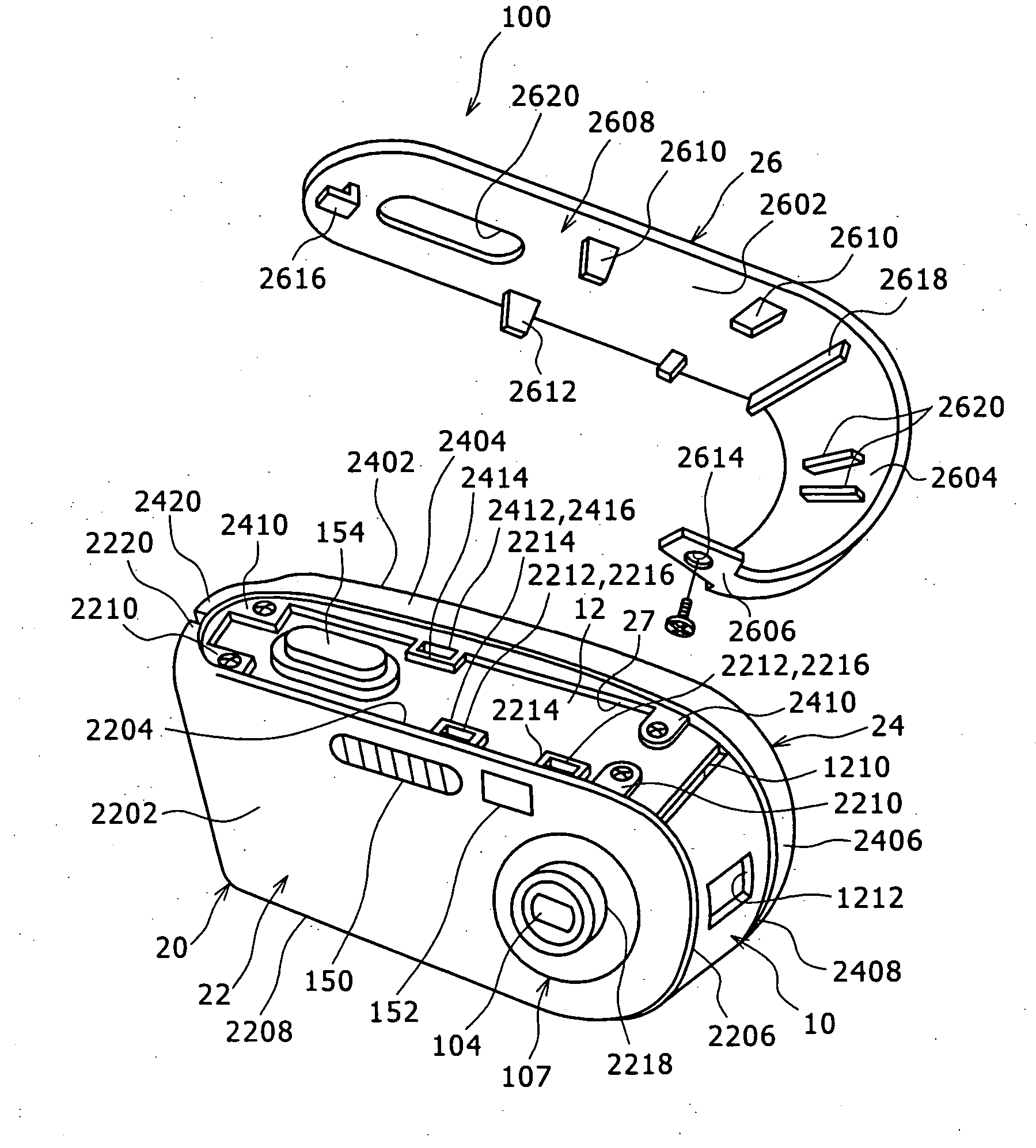
[0036] A digital still camera 100 in a second embodiment according to the present invention will be described with reference to FIGS. 7 and 8, in which parts like or corresponding to those of the digital still camera 100 in the first embodiment are denoted by the same reference characters and the description thereof will be omitted.

[0037]FIG. 7 is an exploded perspective view of the digital still camera 100 in the second embodiment and FIG. 8 is a perspective view of the digital still camera 100 shown in FIG. 7. A case 20 holding a functional unit 10 has a front cover 22 covering the front surface of the functional unit 10, a back cover 24 covering the back surface of the functional unit 10, and a middle cover 26 covering the top, the side and the bottom surface of the functional unit 10. The front cover 22 and the back cover 24 are formed in a single piece so as to define an open space 27. The case 20 is formed by assembling the covers 22, 24 and 26. The functional unit 10 is inse...

third embodiment

[0045] A portable game machine 200 in a third embodiment according to the present invention will be described with reference to FIGS. 9 and 10. FIG. 9 is a perspective view of the game machine 200 in the third embodiment, FIG. 10 is an exploded perspective view of the game machine 200 and FIG. 11 is a sectional view of an essential part of a middle cover 26 included in the game machine 200.

[0046] As shown in FIG. 9, the game machine200 has a functional unit 10 formed by assembling component parts, and a case 20 holding the functional unit 10 therein. The component parts include a control unit that reads game software from a cartridge 220 storing the game software and executes control operations on the basis of the game software, an image processing unit for processing image data processed by the control unit, a display unit including a liquid crystal display 202 for displaying pictures represented by image data processed by the image processing unit, an operating unit including a p...


PUM


Abstract

Disclosed is an electronic device including: a functional unit built by assembling component parts and having a shape substantially resembling a flat, rectangular solid; and a case holding the functional unit therein and having a shape substantially resembling a flat, rectangular solid. In the device, the functional unit has a first major surface, a second major surface opposite the first major surface, and four side surfaces extending between the respective peripheries of the first and the second major surface; and the case has a first cover covering the first major surface of the functional unit, a second cover covering the second major surface of the functional unit, and a third cover covering three continuous ones of the four side surfaces of the functional unit.

Description

CROSS-REFERENCES TO RELATED APPLICATIONS [0001] The present invention contains subject matter related to Japanese Patent Application No. 2005-011872 filed in the Japanese Patent Office on Jan. 19, 2005, the entire contents of which being incorporated herein by reference. BACKGROUND OF THE INVENTION [0002] The present invention relates t an electronic device and a case thereof. [0003] Each of most electronic devices has case holding therein a functional unit formed by assembling component parts of the electronic device. In most cases, the case is built by fastening together a plurality of wall members with screws. The screws fastening together the wall members of the case thus built appear on the surface of the case to spoil the aesthetic appearance of the electronic device. To avoid spoiling the aesthetic appearance of the electronic device, the heads of the screws are covered with concealing caps and concealing plugs attached to the case. Electronic devices having such a case are d...

Claims


Application Information

Patent Timeline
Patent Type & Authority Applications(United States)
IPC IPC(8): G03B17/02
CPCG03B17/04H04N5/2252H04N23/51
Inventor IWATA, KAZUNOBUMATSUYUKI, NAOTOIKARI, TAKESHIISHII, DAISUKE
Owner SONY CORP
Why Eureka
Try Eureka