Stabilized soil structures and facing elements for its construction

a technology of stabilizing soil and facing elements, which is applied in the direction of soil preservation, bulkheads/piles, artificial islands, etc., can solve the problems of poor tolerance of alkaline environments such as those found in concrete, and achieve the effect of facilitating introduction

Active Publication Date: 2006-08-03
TERRE ARMEE INT
View PDF6 Cites 14 Cited by
  • Summary
  • Abstract
  • Description
  • Claims
  • Application Information

AI Technical Summary

Benefits of technology

[0015] The fact that the loop of the strip inside the facing is offset outside the plane of emergence allows this strip to penetrate into the thickness of the facing while remaining oriented in this plane down to a certain depth. This ensures good guiding of the strips as they emerge from the facing and avoids inappropriate stressing of the cast material (generally concrete). This permits good positioning and effective anchoring of the reinforcement strip while ensuring that it does not follow excessively sharp curves and avoiding to subject it to high contraction forces.
[0017] In one embodiment of the structure, the facing has, in the anchoring region, a protective sheath receiving the reinforcement strip along said path. This sheath separates the strip from the cast material so as to protect the reinforcement against premature damage. In particular, if the reinforcement is obtained using polyester fibres, it is known that these poorly tolerate alkaline environments such as those found in concrete. The aforementioned sheath thus complements the protection conferred by the plastic coating on the polyester fibres of the strip.
[0019] When the facing element is manufactured, it is advantageously fitted with an elongated member, such as a cable or rope, inserted within the protective sheath for pulling the reinforcement strip along its path. This facilitates the introduction of the strip, which can take place on the construction site so that the need to store and transport the facing elements equipped with their reinforcement strips can be avoided.

Problems solved by technology

In particular, if the reinforcement is obtained using polyester fibres, it is known that these poorly tolerate alkaline environments such as those found in concrete.

Method used


Image

  • Stabilized soil structures and facing elements for its construction
  • Stabilized soil structures and facing elements for its construction
  • Stabilized soil structures and facing elements for its construction

Examples


Embodiment Construction

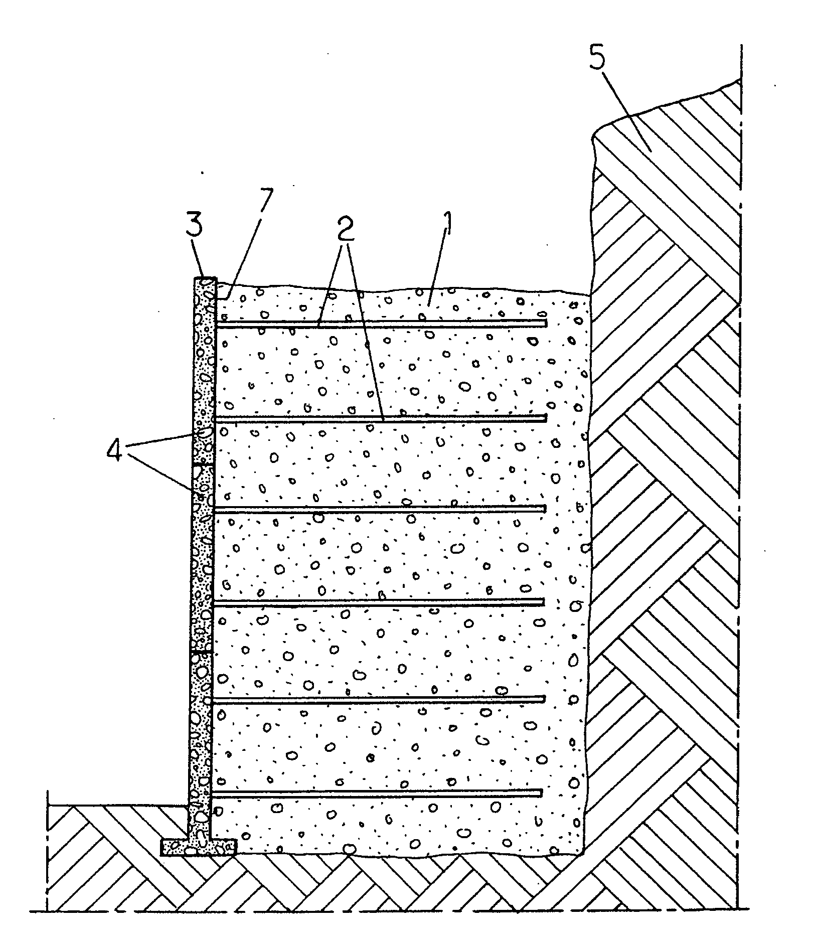
[0032]FIG. 1 illustrates the application of the invention to the building of a stabilized soil retaining wall. A compacted fill 1, in which reinforcements 2 are distributed, is delimited on the front side of the structure by a facing 3 formed by juxtaposing prefabricated elements 4 in the form of panels, and on the rear side by the soil 5 against which the retaining wall is erected.

[0033] The reinforcements 2 comprise synthetic reinforcing members in the form of flexible strips extending in horizontal planes behind the facing 3. These may in particular be reinforcement strips based on polyester fibres encased in polyethylene.

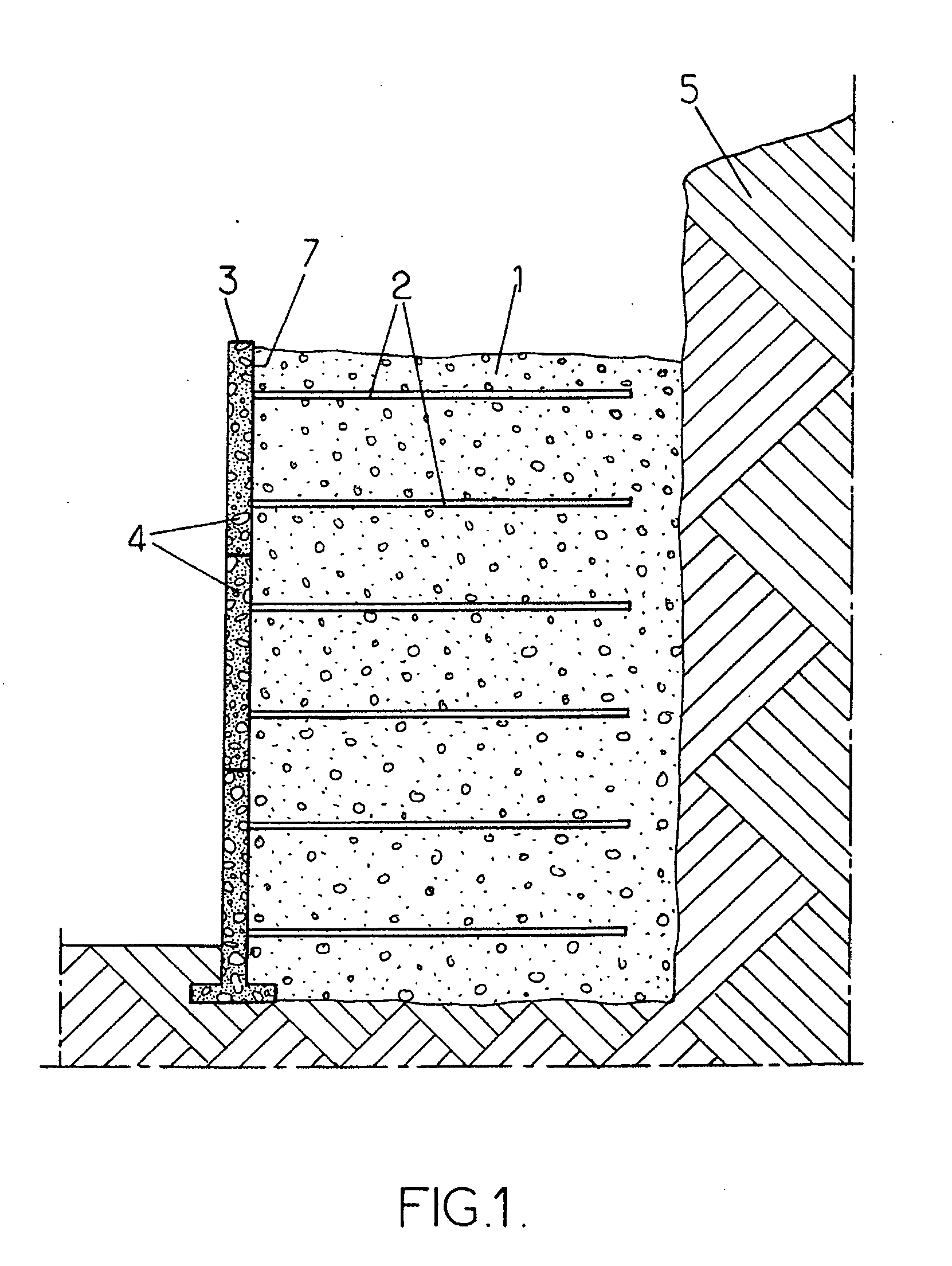
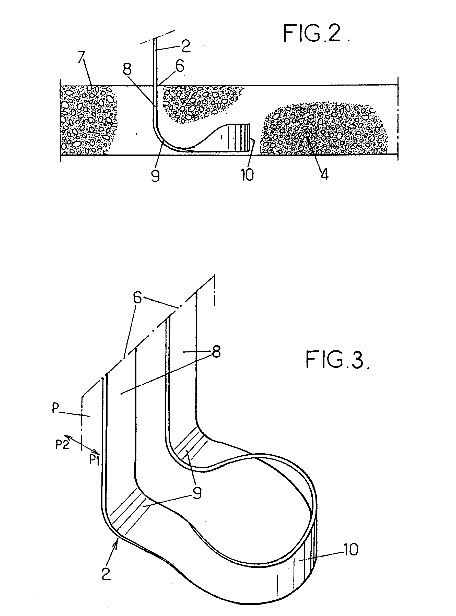
[0034] The reinforcement strips 2 are attached to the prefabricated elements 4 joined together to form the facing 3. These elements 4 are typically made of reinforced concrete. In the example shown, they are in the form of panels. They could also have other forms, in particular the form of blocks. When the concrete of such an element 4 is cast, one or more rei...


PUM


Abstract

The facing element for a stabilized soil structure comprises a body of cast material inside which a path is formed for a reinforcement strip between two points of emergence situated on a rear face of the element. This path includes two rectilinear portions which are respectively adjacent to the two points of emergence and are each arranged so as to position the strip in the same plane of emergence perpendicular to the rear face, two curved portions which respectively continue the two rectilinear portions and are arranged so as to deviate the strip from the plane of emergence, and a connection portion which joins the two curved portions to one another and has at least one loop situated outside the plane of emergence.

Description

CROSS REFERENCE TO RELATED APPLICATION [0001] This is a continuation-in-part application of Ser. No. 11 / 072,954, filed Mar. 3, 2005, entitled “Stabilized Soil Structure and Facing Elements for its Construction” for which priority is claimed and which is incorporated herewith by reference. BACKGROUND OF THE INVENTION [0002] The present invention relates to the construction of stabilized soil or reinforced earth structures. This building technique is commonly used to produce structures such as retaining walls, bridge abutments, etc. [0003] A stabilized soil structure combines a compacted fill, a facing, and reinforcements usually connected to the facing. The reinforcements are placed in the soil with a density dependent on the stresses that might be exerted on the structure, the thrust forces of the soil being reacted by the soil-reinforcements friction. [0004] The invention more particularly concerns the case where the reinforcements are in the form of strips of synthetic material, f...

Claims


Application Information

Patent Timeline
Patent Type & Authority Applications(United States)
IPC IPC(8): E21D20/00E02D5/00
CPCE02D29/0225E02D29/0241
Inventor FREITAG, NICOLASMORIZOT, JEAN-CLAUDE
Owner TERRE ARMEE INT
Why Eureka
Try Eureka