Marine elastic coupling

a technology of elastic coupling and elastic coupling, which is applied in the direction of yielding coupling, shafts, bearings, etc., can solve the problems of increasing torsional rigidity not high enough to sufficiently reduce the resonance phenomena in the propeller transmission system during high-speed travel, and the effect of absorbing torque variation and low torsional rigidity

Inactive Publication Date: 2006-08-03
KANZAKI KOKYUKOKI MFG
View PDF2 Cites 7 Cited by
  • Summary
  • Abstract
  • Description
  • Claims
  • Application Information

AI Technical Summary

Benefits of technology

[0022] With the aforementioned configuration according to the invention, when a propeller shaft frequently repeats forward and reverse rotations at low speeds, e.g., when a boat leaves or reaches the shore, the elastic coupling exhibits low torsional rigidity to effectively absorb torque variation. In this way, the elastic coupling reduces the noise generated by the reversing gear, etc., thereby providing a comfortable ride. On the other hand, when the boat travels at high speeds, the elastic coupling exhibits higher torsional rigidity to avoid resonance phenomena attributed to torsional vibrations, thereby preventing damage or failure of various components in the drive system.
[0023] High torsional rigidities obtained during such high-speed travel may be defined as values near the proportional limit of each of the elastic bodies constituting the elastic coupling. This minimizes elastic deformation of the elastic bodies when the torsional rigidity of the elastic coupling is high. Consequently, the torsional rigidity of the elastic coupling can be increased to lower the vibration-absorbing capability of the elastic bodies during high-torque transmission, so as to further avoid such resonance phenomena.
[0024] The above-described effects can be ensured by making the torsional rigidity during high-torque transmission not less than 100 times greater than that of the torsional rigidity during low-torque transmission. In particular, the torsional rigidity during high-torque transmission may be 300 times greater than the torsional rigidity during low-torque transmission. This significantly reduces the vibration-absorbing capability of the elastic bodies during high-torque rotation, so as to effectively avoid resonance phenomena.
[0025] It is possible to easily control variations of the torsional rigidity of the elastic coupling by using rubber-material bodies as the elastic bodies, adjusting the dimensional relationship between these elastic bodies and both the inner and outer wheels in which the elastic bodies are accommodated, and making the elastic bodies have different elasticities by choice of the rubber materials. When an elastic body of a single kind of rubber material includes a hard material accommodated therein, the thickness of the elastic block upon elastic deformation is thin, causing an abrupt change in elasticity after the deformation of the elastic portion. Consequently, the elastic coupling provides a high torsional rigidity more reliably during high-speed travel.
[0026] The marine elastic coupling according to the invention can be easily employed in a variety of large and small vessels having a reduction and reversing gear.

Problems solved by technology

Therefore, with a conventional elastic coupling, resonance phenomena is likely to occur because of the low torsional rigidity during transmission of a high torque, e.g., high-rotation torque needed when a boat travels at high speeds.
This causes abnormal vibrations during high-speed travel to cause damage or failure of the mechanism or various components of the drive system.
However, for example, as indicated by the graph of FIG. 17 showing the correlation between torsional rigidity and torque, the increases in the torsional rigidity are not high enough to sufficiently reduce the resonance phenomena in the propeller transmission system during high-speed travel.

Method used


Image

  • Marine elastic coupling
  • Marine elastic coupling
  • Marine elastic coupling

Examples


Embodiment Construction

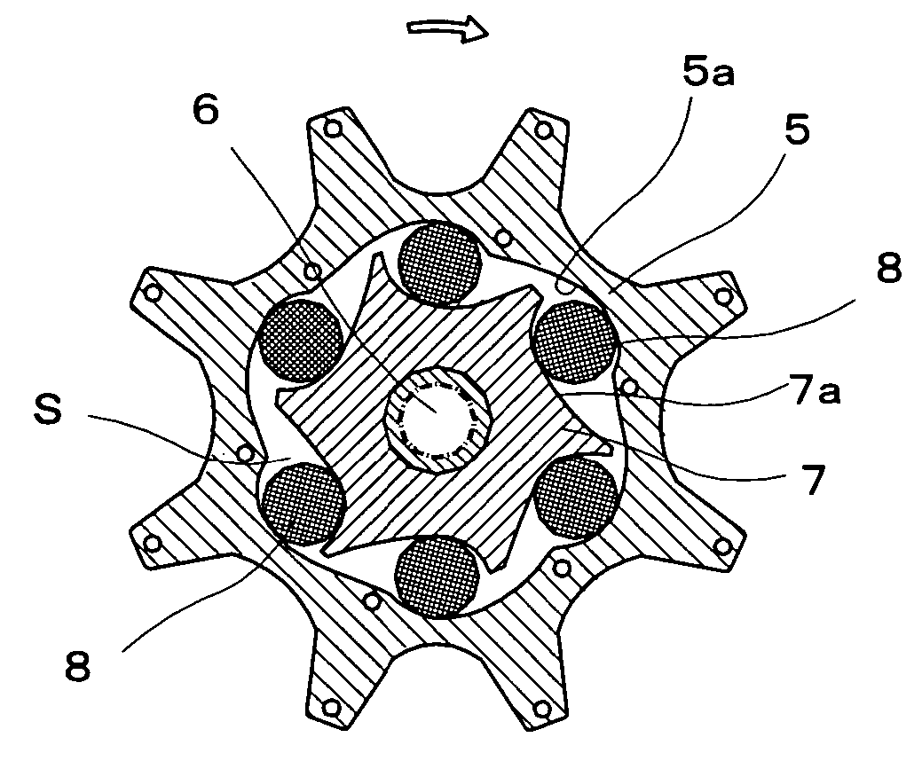
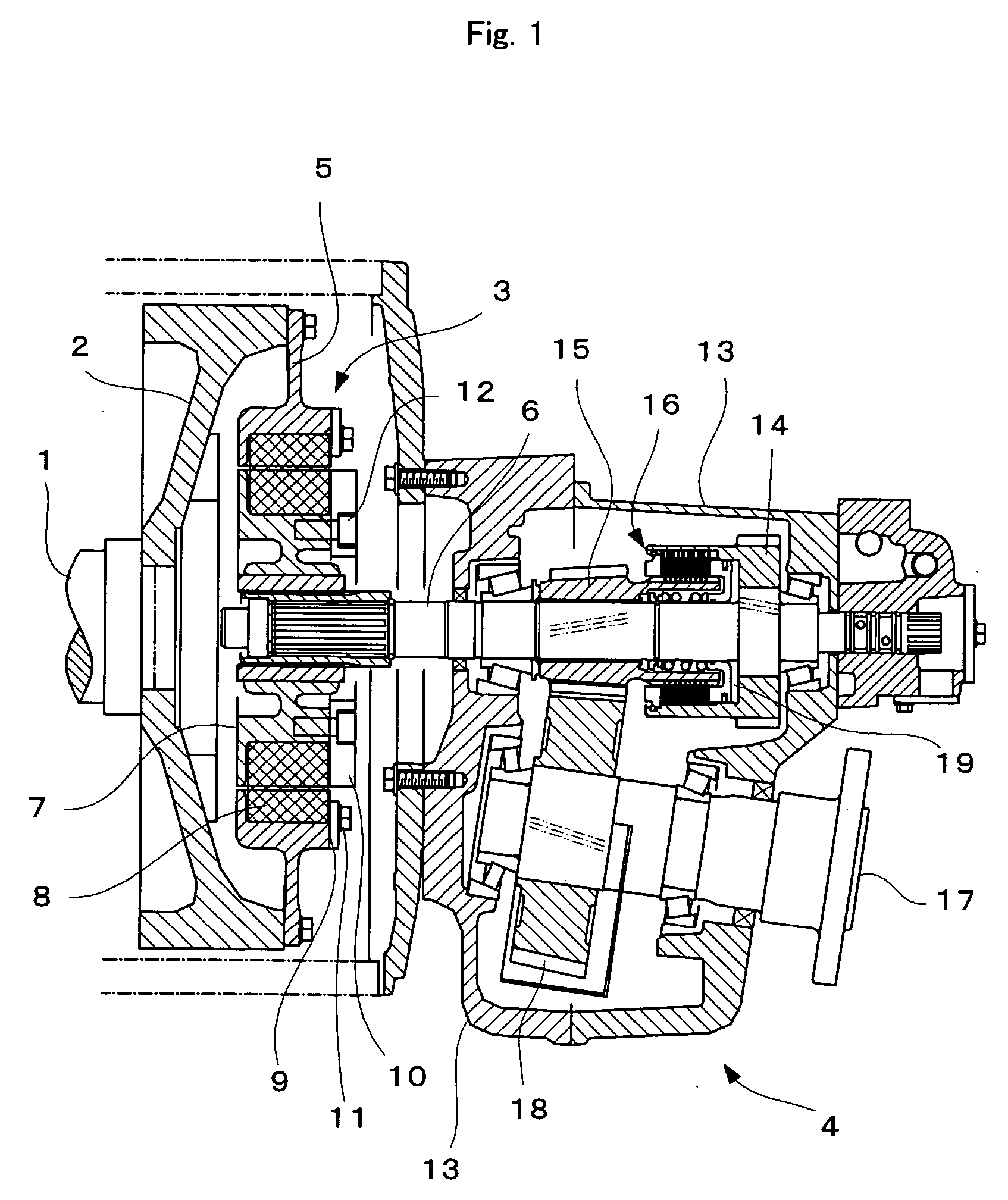
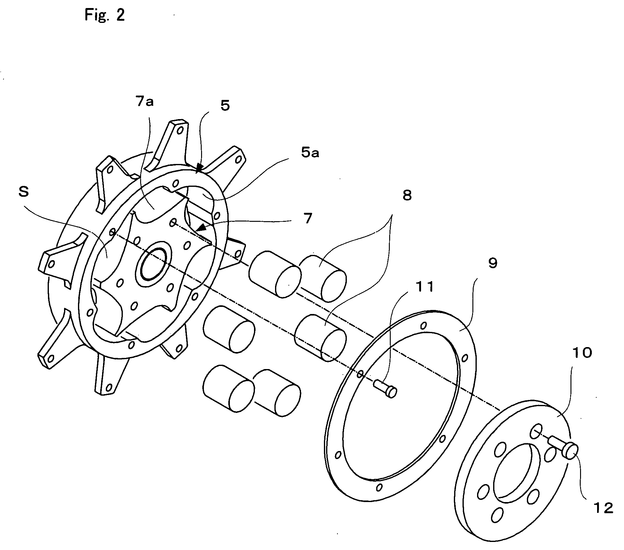
[0044]FIG. 1 is a vertical cross section showing the principal part of a marine elastic coupling; FIG. 2 is an exploded perspective view showing the elastic coupling portion; and FIG. 3 is a cross section. showing the elastic coupling portion.

[0045] Referring to FIG. 1, a flywheel 2 is mounted on a drive shaft 1 which is coupled to an engine outside the figure, and an elastic coupling 3 is arranged concentrically with a central portion of the flywheel 2. The elastic coupling 3 is connected to an input shaft 6 of a marine gear 4. Note that the propeller shaft and the propeller are omitted in FIG. 1.

[0046] The marine gear 4 comprises a casing 13; the input shaft 6 inserted into an opening at one end of the casing 13; a forward housing gear 14 secured to the input shaft 6; a forward pinion gear 15 rotatably fitted over the input shaft 6; a friction clutch 16 disposed between the forward housing gear 14 and the forward pinion gear 15; an output shaft 17 projecting through an opening a...


PUM


Abstract

An object of the present invention is to provide improved torsional rigidity of an elastic coupling for use in a marine engine which couples an engine to a reversing gear. The elastic coupling comprises at least one low-rigidity element providing torsional rigidity during transmission of a predetermined low torque; and at least one high-rigidity element providing, during transmission of a predetermined high torque, torsional rigidity higher than that provided by the low-rigidity element.

Description

TECHNICAL FIELD [0001] The present invention relates to a marine elastic coupling which transmits engine power to the propeller of a vessel. BACKGROUND OF THE INVENTION [0002] An engine mounted in a vessel such as a pleasure boat, fishing boat, etc. is connected, via a flywheel arranged concentrically with a drive shaft and a coupling such as an elastic coupling (see, for example, JP 1995-35150 A and U.S. Pat. No. 6,244,964), to a marine gear which in turn is connected to a propeller shaft. Engine output is thus transmitted via the drive shaft, flywheel, elastic coupling, and marine gear to the propeller shaft, all of which constitute a marine drive system (see, for example, U.S. Pat. No. 4,679,673). [0003] The elastic coupling serves to absorb the shock caused by torque variations when the engine is used by frequently repeating forward and reverse rotations at low speeds, e.g., when a boat leaves or reaches the shore. The elastic coupling thus reduces noise caused by the reversing ...

Claims


Application Information

Patent Timeline
Patent Type & Authority Applications(United States)
IPC IPC(8): F16D3/00
CPCF16D3/58F16D3/68
Inventor NAKAGAWA, SHIGEAKIIMANAKA, TOSHIO
Owner KANZAKI KOKYUKOKI MFG
Why Eureka
Try Eureka