AI technical title is built by PatSnap AI team. It summarizes the technical point description of the patent document.
a technology of a clinical apparatus and a cylinder, which is applied in the field of clinical equipment, can solve the problems of inability to use a technique, low spatial resolution of the measured elastic constant and visco elastic constant from the shear wave velocity, and many independent deformations in the past technique, so as to reduce the amount of calculation, simplify the calculation process, and improve the measurement accuracy of displacement vector distribution.
Active Publication Date: 2006-08-03
SUMI CHIKAYOSHI
View PDF5 Cites 69 Cited by
Summary
Abstract
Description
Claims
Application Information
AI Technical Summary
This helps you quickly interpret patents by identifying the three key elements:
Problems solved by technology
Method used
Benefits of technology
Benefits of technology
[0020] The third purpose of the present invention is to improve the measurement accuracy of displacement vector distribution generated in 3D, 2D (including or not including beam direction), or 1D (beam direction or scan direction) ROI in the target body when the gradient of the echo cross-spectrum phase is estimated. The cross-spectrum can also be estimated by Fourier's transform of the echo cross-correlation function.
[0021]
Problems solved by technology
The disadvantages of the past measurement technique is that the past technique requires many independent deformation fields generated by mechanical sources outside the target body.
However, if there exist internal mechanical sources and/or mechanical sources are uncontrollable, the technique becomes unavailable.
Furthermore, the spatial resolutions of measured elastic constants and visco elastic constants from the shear wave velocity are very low.
However, these techniques require other physical properties of the target tissue to measure the temperature.
If the degeneration occurs in the region, the physical properties also change; thus causing severe limitations of the temperature measure
Method used
Image
Click on the blue label to locate the original text in one second.
Reading with bidirectional positioning of images and text.
Examples
Embodiment Construction
[0069] The following is explanation in detail of conduct forms of the present invention with referring to figures.
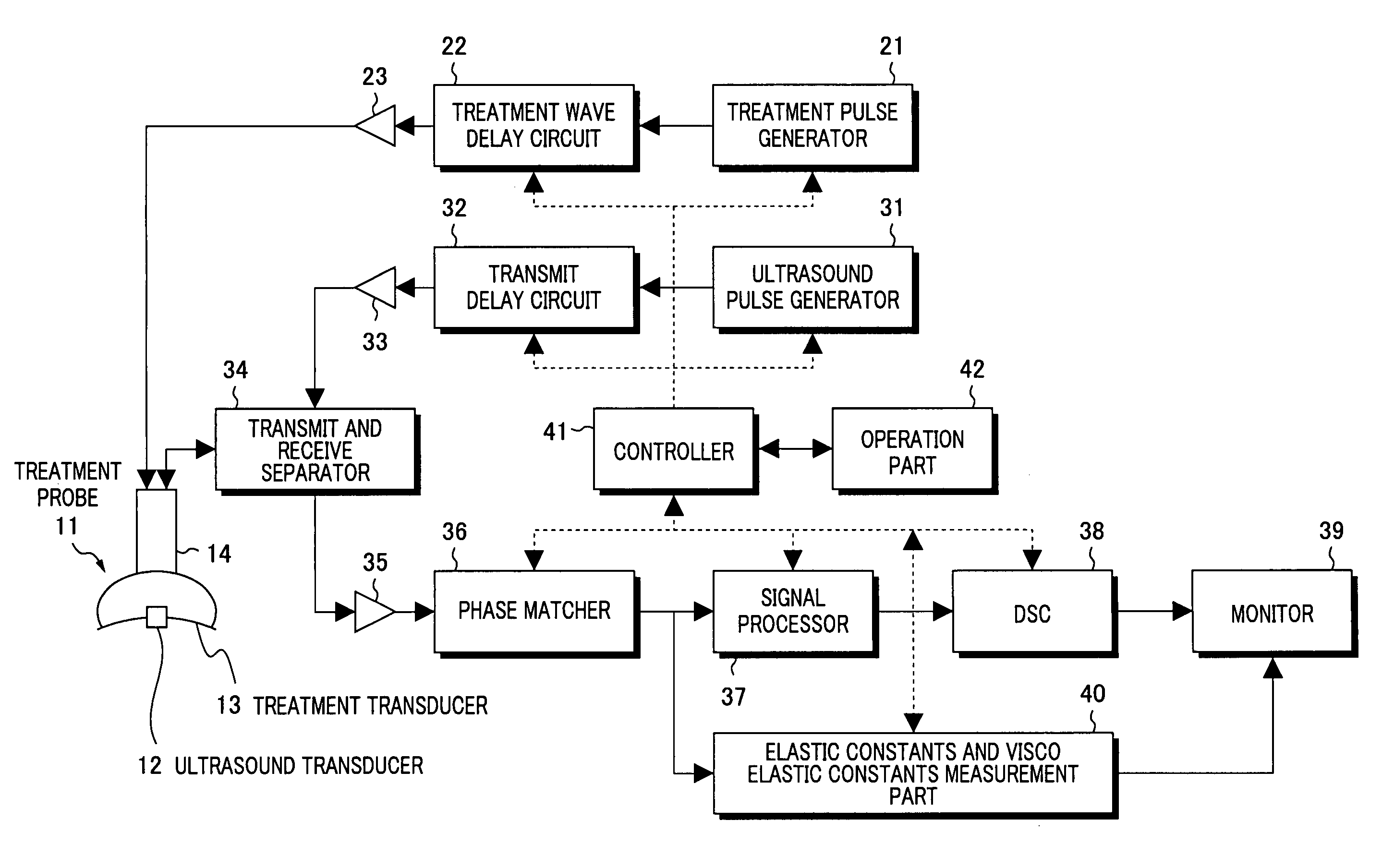
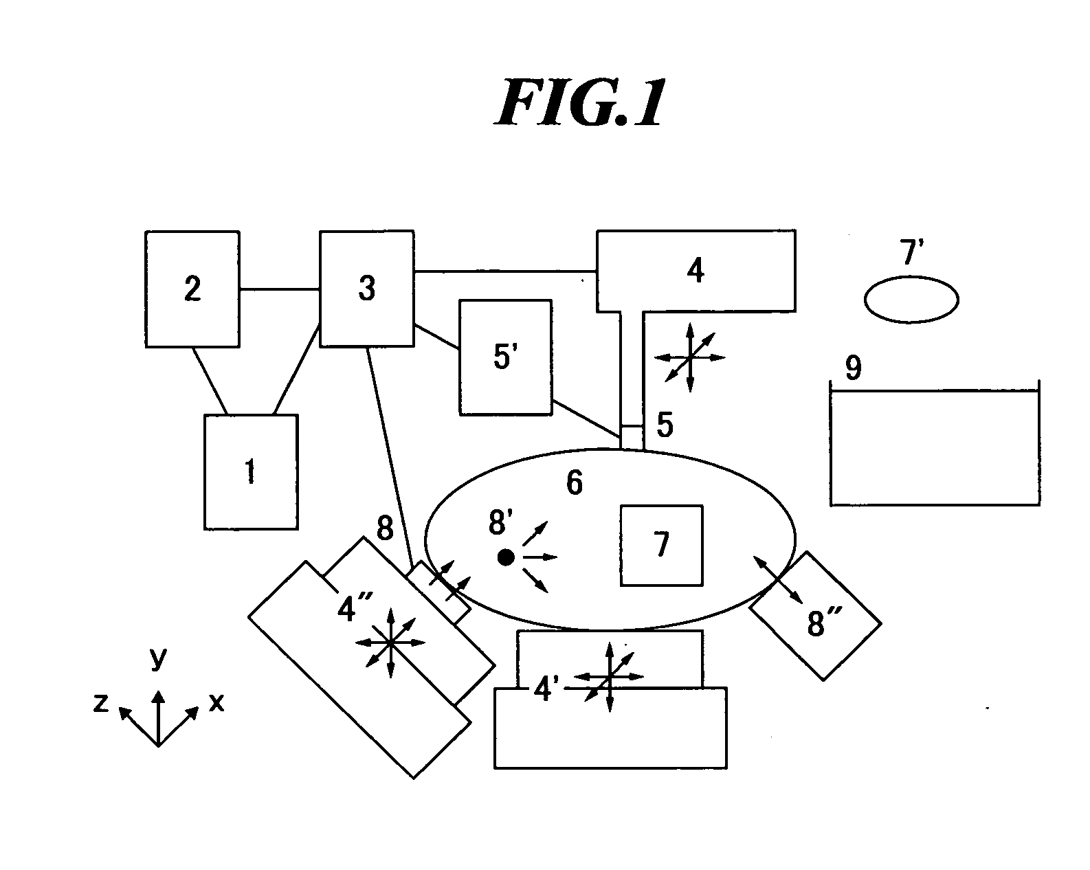
[0070]FIG. 1 shows a schematic representation of a global frame of the displacement vector and strain tensor measurement apparatus, and the elasticity and visco-elasticity constants measurement apparatus, related to one of conduct forms of the present invention. This apparatus measures in 3D, 2D, or 1D ROI 7 set in the measurement object 6 the displacement vector component distributions, strain tensor component distributions, their time-space partial derivative distributions, etc. to obtain the strain tensor field, strain rate tensor field, acceleration vector etc., from which this apparatus measures the following constant distributions, i.e. elastic constants such as shear modulus, Poisson's ratio, etc., visco elastic constants such as visco shear modulus, visco Poisson's ratio, etc., delay times or relaxation times relating these elastic constants and visco elastic co...
PUM
Abstract
The present invention provides elastic constant and visco elastic constant measurement apparatus etc. for measuring in the ROI in living tissues elastic constants such as shear modulus, Poisson's ratio, Lame constants, etc., visco elastic constants such as visco shear modulus, visco Poisson's ratio, visco Lame constants, etc. and density even if there exist another mechanical sources and uncontrollable mechanical sources in the object. The elastic constant and visco elastic constant measurement apparatus is equipped with means of data storing 2 (storage of deformation data measured in the ROI 7 etc.) and means of calculating elastic and visco elastic constants 1 (calculator of shear modulus etc. at arbitrary point in the ROI from measured strain tensor data etc.), the means of calculating elastic and visco elastic constants numerically determines elastic constants etc. from the first order partial differential equations relating elastic constants etc. and strain tensor etc.
Description
BACKGROUND OF THE INVENTION [0001] 1. Field of the Invention [0002] The present invention relates to apparatuses and methods for low-destructively or low-invasively measuring mechanical properties within object such as structures, substances, materials, living tissues (liver, prostate, breast, bone, etc.). For instance, measured can be, due to applied stress and / or vibration by arbitrary mechanical sources, the generated displacement vector, strain tensor, strain rate tensor, acceleration vector or velocity vector within the body. Furthermore, from the measured deformation data, the following constants can be measured, i.e., elastic constants such as shear modulus, Poisson's ratio, etc., visco elastic constants such as visco shear modulus, visco Poisson's ratio, etc., delay times or relaxation times relating these elastic constants and visco elastic constants, or density. [0003] In typical applied fields, e.g., in a medical field such as ultra sonic diagnosis, nuclear magnetic reson...
Claims
Application Information
Patent Timeline
Application Date:The date an application was filed.
Publication Date:The date a patent or application was officially published.
First Publication Date:The earliest publication date of a patent with the same application number.
Issue Date:Publication date of the patent grant document.
PCT Entry Date:The Entry date of PCT National Phase.
Estimated Expiry Date:The statutory expiry date of a patent right according to the Patent Law, and it is the longest term of protection that the patent right can achieve without the termination of the patent right due to other reasons(Term extension factor has been taken into account ).
Invalid Date:Actual expiry date is based on effective date or publication date of legal transaction data of invalid patent.

