Video node for wireless mesh network

a wireless mesh network and video node technology, applied in the field of wireless mesh network communication, can solve the problems of time-consuming and laborious setting up, inconvenient installation, and inability to meet the needs of video surveillance operations

Inactive Publication Date: 2006-08-10
AGILEMESH
View PDF7 Cites 89 Cited by
  • Summary
  • Abstract
  • Description
  • Claims
  • Application Information

AI Technical Summary

Problems solved by technology

Such a combination of separate components do not serve the purpose of video surveillance very well due to the requirement for the user to interconnect and configure each of the components separately.
Such configurations often occupy considerable space which does not lend itself well to surveillance operations.
Additionally, a surveillance operation of a public event may involve network nodes that are located in places where access can be a problem.
Setting up is time consuming and laborious, not to mention inconvenient, to configure devices to provide a wireless mesh video network.
In addition, it is not unusual for an address or encryption code to be incorrectly assigned, thus rendering a node completely inaccessible from the network.
Correction of these types of errors are often difficult and laborious.
Additionally, many potential users of a wireless video mesh network may not have a strong understanding of digital wireless networks necessary for their set up and maintenance.
Determining what address to assign each device is often not easy and generally requires that the user have a strong understanding of networking concepts.
While peripheral devices do sometimes have the capability of requesting and receiving a network address automatically, determination of just what IP address was assigned is often difficult.
Another issue when deploying a mesh network involves optimal positioning of each node.
This can be a time consuming task and usually requires special tools such as a location analyzer.
Such tools are costly and require RF and network knowledge to operate.

Method used


Image

  • Video node for wireless mesh network
  • Video node for wireless mesh network
  • Video node for wireless mesh network

Examples


Embodiment Construction

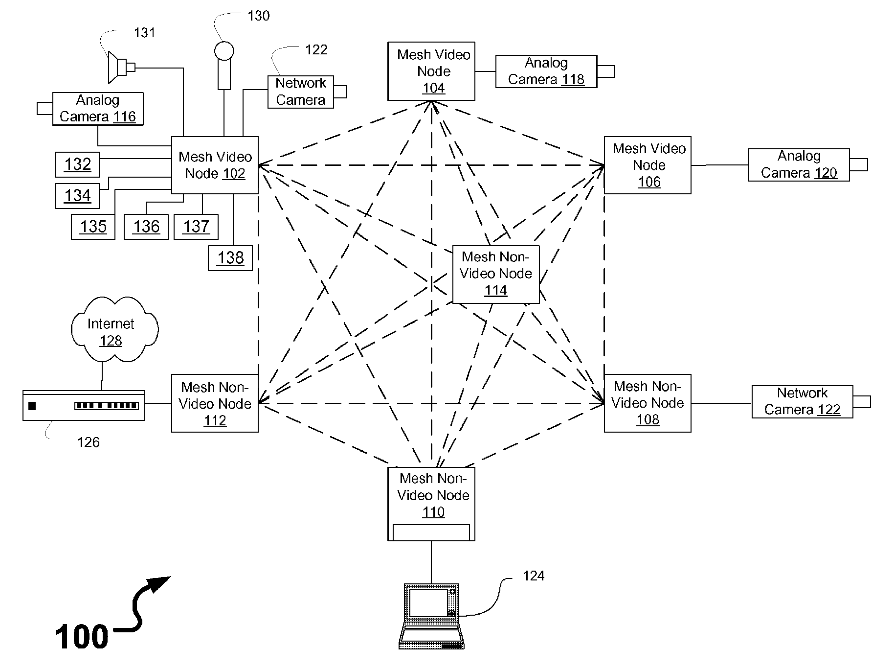
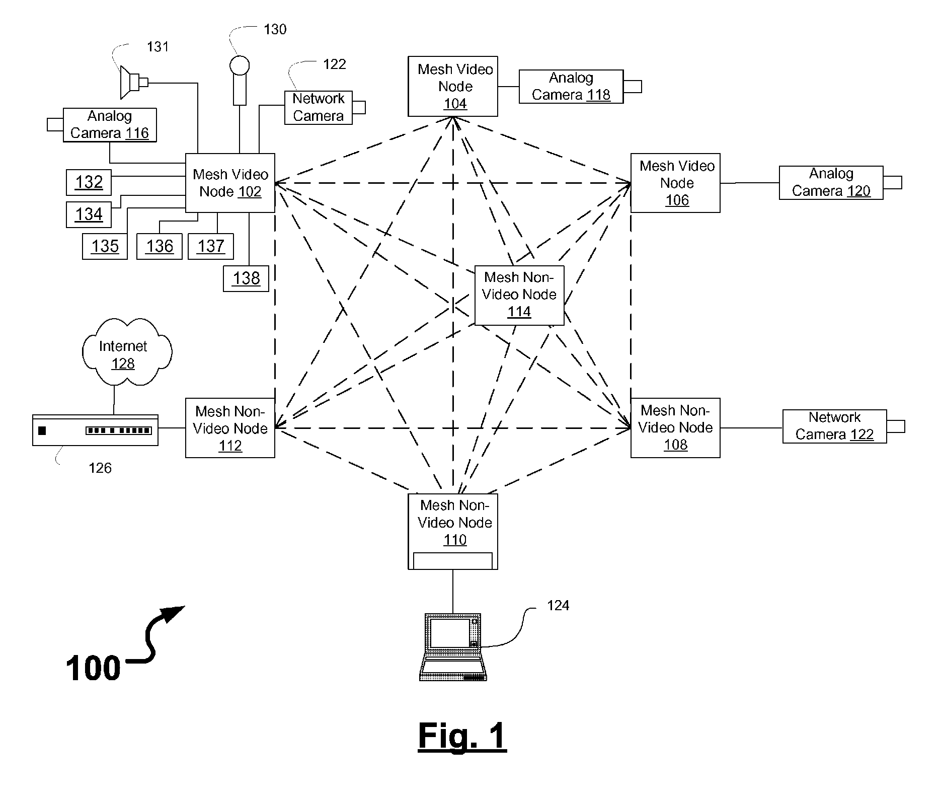
[0024]FIG. 1 is a schematic block diagram illustrating a communications network 100 that includes a plurality of wireless mesh nodes 102-114 and a network hardware component 126. Wireless mesh nodes 102-114 include wireless multimedia nodes 102-106 and wireless non-video nodes 108-114.

[0025] Surveillance devices may be coupled to wireless mesh nodes 102-108, and may include analog video cameras 116-120 (coupled via a video cable), network video camera 122 (coupled via an Ethernet link), microphone 130, speaker 131, gas detector 132, biohazard detector 134, radiation detector 135, break-glass detector 136, panic alarm button 137, keypad 138, motion detectors (not shown), open door detectors (not shown), et cetera. Other devices may be coupled to wireless mesh non-video nodes 110-114 such as laptop computer 124 or other computers and other network devices (not shown). Laptop computer 124 may be used as to manage multimedia inputs and outputs in the communications network 100, for exa...


PUM


Abstract

Provided are mesh video nodes for wireless mesh networks and methods thereof. A mesh video node includes a wireless interface unit, a multimedia processing unit, an input / output unit, and a control panel interface unit. The mesh video node is configured via a user interface with a communications channel selector and a node selector, where each channel is associated with a predetermined frequency channel, and each node is associated with an internet protocol address. A method of deployment is also provided via a user interface that visually represents link qualities between neighboring nodes.

Description

CROSS REFERENCE TO RELATED APPLICATIONS [0001] This Application claims the benefit of U.S. Provisional Application Ser. Nos. 60 / 650,112, filed on Feb. 7, 2005, and entitled “Wireless digital video network node,” 60 / 650,113, filed on Feb. 7, 2005, and entitled “Addressing mechanism for interconnecting network devices across a mesh network to the internet,” 60 / 650,114, filed on Feb. 7, 2005, and entitled “Wireless digital video node user interface,” and 60 / 650,110, filed on Feb. 7, 2005, entitled “Built-in deployment tools,” which are commonly assigned with the present application and incorporated herein by reference.BACKGROUND OF THE INVENTION [0002] 1. Technical Field [0003] Disclosed embodiments relate generally to wireless networking, and more specifically relate to communicating multimedia data over wireless mesh networks. [0004] 2. Description of Related Art [0005] Mesh networks are known to be used in a wide variety of applications. For instance, mesh networks have been known t...

Claims


Application Information

Patent Timeline
Patent Type & Authority Applications(United States)
IPC IPC(8): H04L12/16H04Q7/24H04L12/66H04W84/18H04W88/04
CPCG08B13/19656G08B13/1966H04L41/0803H04L41/18H04L41/22H04N7/181H04N7/185H04W84/18H04W88/04H04L67/36H04L67/75
Inventor DICKERSON, JAMES W.CROMWELL, MARK C.SMITH, DENNIS K.
Owner AGILEMESH
Why Eureka
Try Eureka