
Plain bearing element and method of producing a wrapped plain bearing bushing

a technology of plain bearings and components, applied in the direction of bearings, shafts, mechanical equipment, etc., can solve the problems of complex production of composite material bushings with sliding material plugs

Active Publication Date: 2006-08-10
FEDERAL MOGUL DEVA
View PDF12 Cites 10 Cited by
  • Summary
  • Abstract
  • Description
  • Claims
  • Application Information

AI Technical Summary

Benefits of technology

[0008] The invention provides a method with which bushings having plugs exhibiting sliding material characteristics may be produced economically. The invention also provides reasonably priced sliding elements.
[0016] For the first time, the method according to the invention makes it possible to produce bushings with holes filled with plastics material which exhibit wall thicknesses of 55 mm.
[0020] The protrusion is advantageously provided with a sharp-edged tip. This simplifies insertion of the plugs, because the protrusion is able to cut into the plug material.
[0022] The flanks of the protrusion are advantageously rounded and merge into the contour of the hole. This has the advantage that complete filling of the hole with plug material is simplified and the plug material rests tight against the hole contour in the area of the protrusion.
[0031] The holes may be offset relative to one another. The arrangement and number of plugs depends on the field of application. An offset, in particular overlapping, arrangement of the holes and thus of the plugs has the advantage that the plugs come into contact with the largest possible area of the rotating journal during rotation of the bushing.

Problems solved by technology

Such composite material bushings with sliding material plugs are complex to produce, because the bores can only be introduced after manufacture of the bushing blank.

Method used


Image

  • Plain bearing element and method of producing a wrapped plain bearing bushing
  • Plain bearing element and method of producing a wrapped plain bearing bushing
  • Plain bearing element and method of producing a wrapped plain bearing bushing

Examples


Embodiment Construction

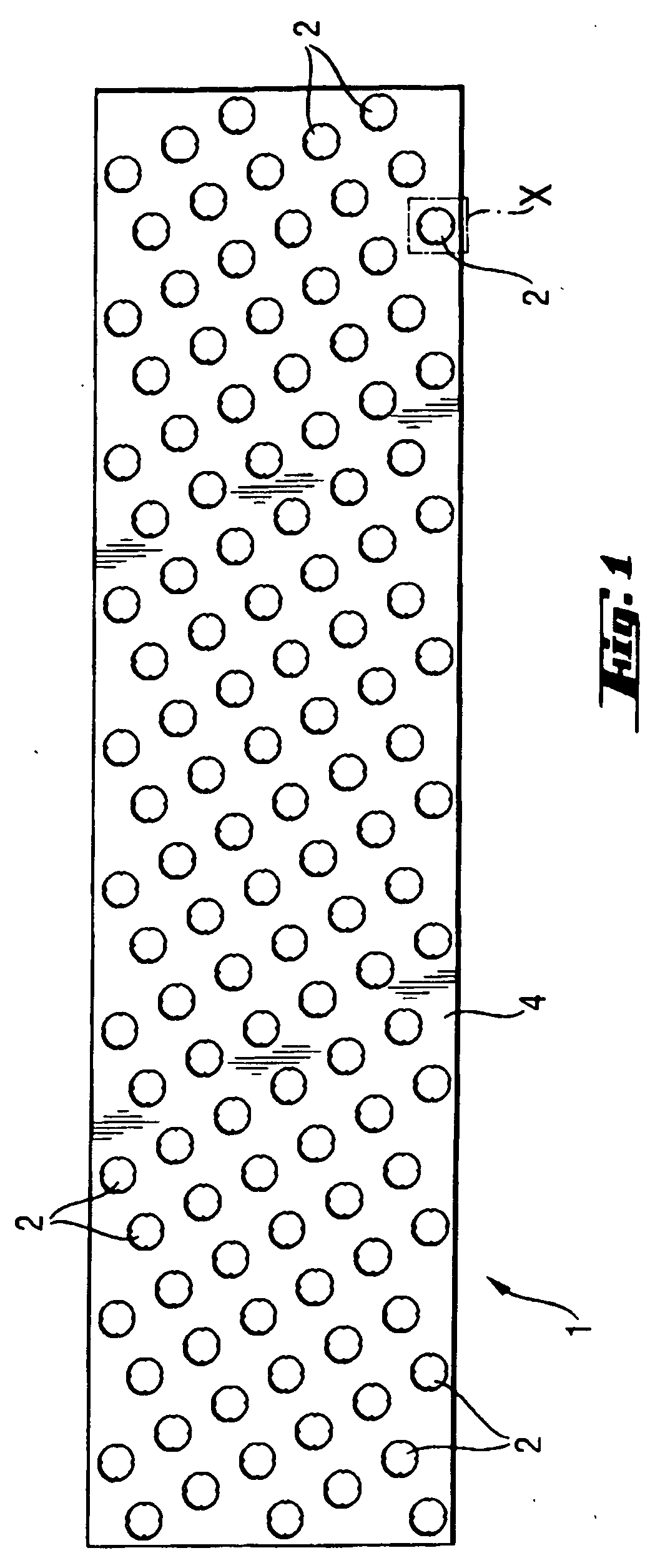
[0043]FIG. 1 shows a plan view of a blank 1 made of the substrate material 4. The blank is rectangular, such that a cylindrical bushing may be produced therefrom. The blank comprises holes 2, which are distributed regularly over said blank. The holes are in an offset and overlapping arrangement, wherein the offset in the transverse direction (perpendicular to the longitudinal direction of the blank) is less than half the hole spacing.

[0044] The blank 1 and thus the substrate material 4 may consist of the following alloys; CuSn7ZnPb, CuAl10Ni, CuSn12.

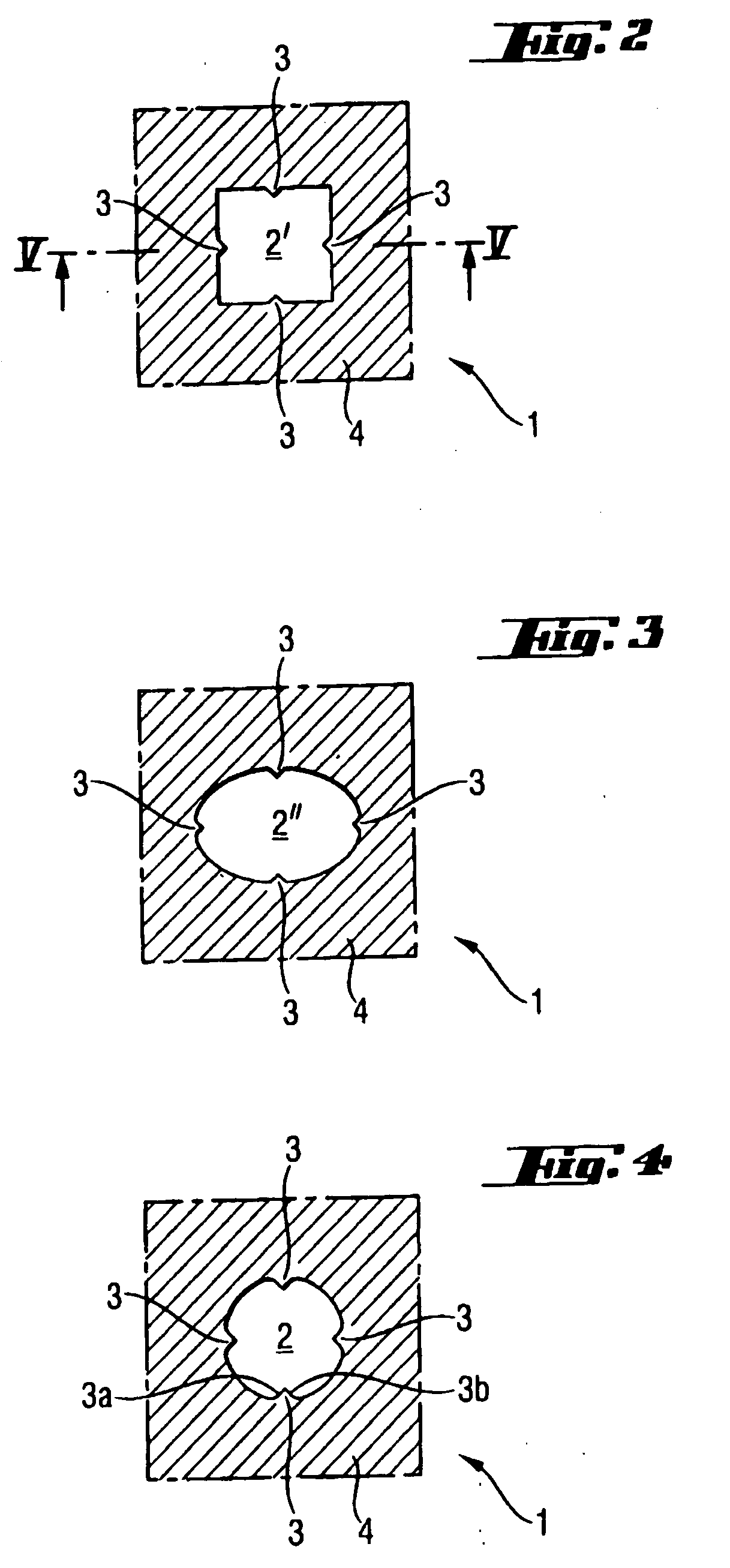
[0045] FIGS. 2 to 4 show various hole shapes on an enlarged scale. FIG. 2 shows a square hole 2′ with four protrusions 3, wherein a protrusion 3 is arranged on each side face of the hole 2′.

[0046]FIG. 3 shows an oval hole 2″ likewise with four protrusions 3 distributed evenly around the periphery of the hole.

[0047]FIG. 4 shows a round hole 2 likewise with our protrusions 3 distributed evenly around the periphery. In plan view, the pr...


PUM

PropertyMeasurementUnit
diametersaaaaaaaaaa
thicknessaaaaaaaaaa
thicknessesaaaaaaaaaa

Abstract

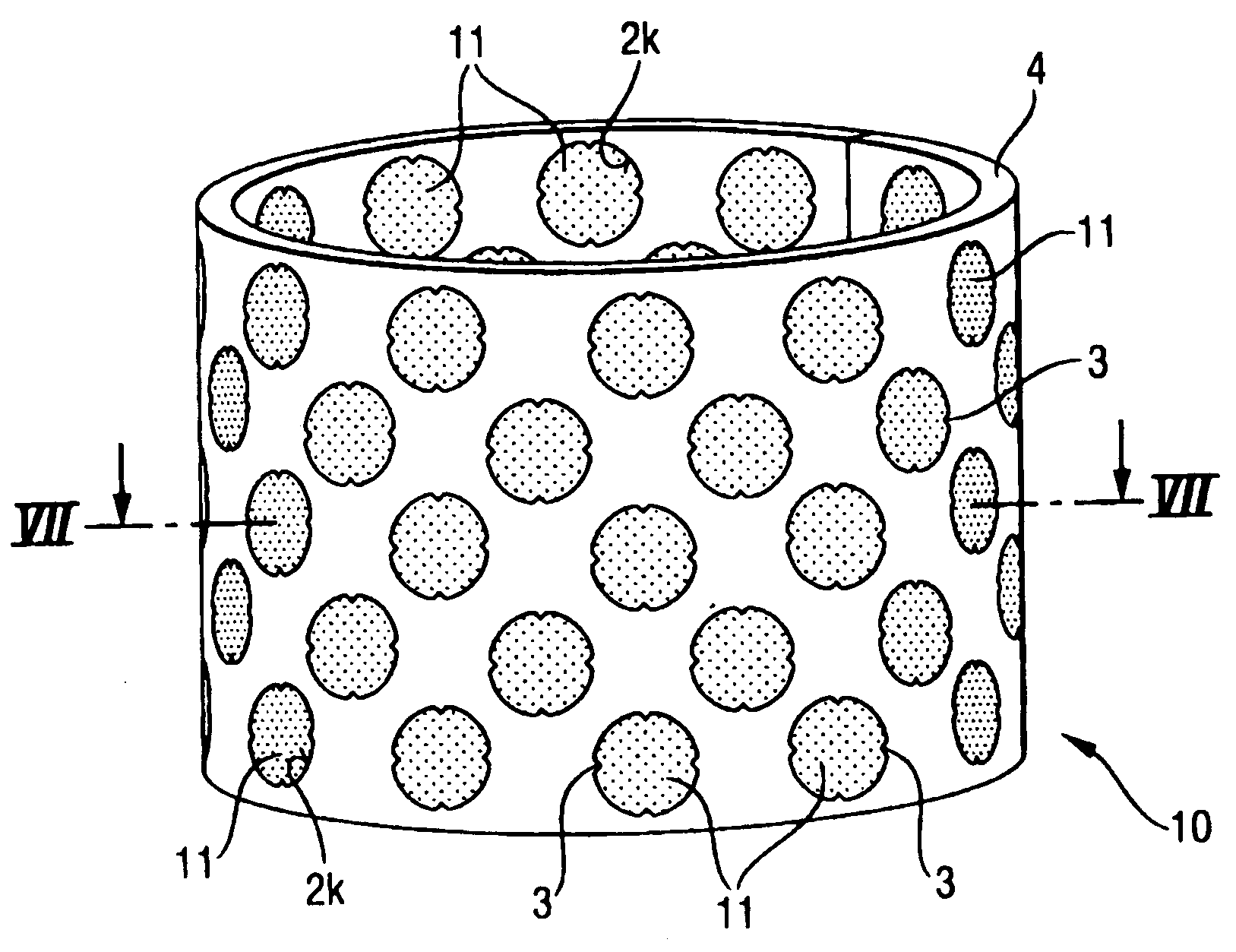
A method for producing a wrapped bushing, includes cutting a metal blank to size: introducing holes into the blank, each hole being provided with at least one inwardly projecting protrusion: inserting plugs of plastics material exhibiting sliding characteristics into the holes; and shaping the blank to form the bushing. The resultant bushing has a substrate of at least one metal in which the holes are provided and filled with the plastics material. Each hole comprises at least one inwardly projecting protrusion.

Description

[0001] This application claims priority to German Patent Application No. 10 2004 060 258.1-14, filed Dec. 15, 2004. BACKGROUND OF THE INVENTION [0002] 1. Technical Field [0003] The invention relates to a method of producing a plain bearing bushing. The invention also relates to a plain bearing element having a substrate material of metal, which comprises holes filled with a plastics material exhibiting sliding characteristics. [0004] Plain bearing elements are in particular plain bearing bushing, thrust washers and flat sliding elements. [0005] 2. Related Art [0006] A wrapped, metal / plastics composite bushing is known from EP 0 802 338 B1, production of which starts from a metallic blank containing holes, the blank being formed into a round shape such that the holes are deformed conically towards the center of the bushing. The overlay is then injected into place in an injection molding or transfer molding machine, wherein the holes are filled to anchor the overlay. [0007] On the oth...

Claims


Application Information

Patent Timeline
Patent Type & Authority Applications(United States)
IPC IPC(8): F16C33/10F16C33/06
CPCB21D53/10F16C33/24F16C2204/12F16C2208/32
Inventor STADLMAYR, AUGUSTSCHMIDT, ACHIM
Owner FEDERAL MOGUL DEVA
Learn More