Hub unit

a technology of hub unit and hub plate, which is applied in the direction of bearing unit rigid support, mechanical equipment, transportation and packaging, etc., can solve the problems of rust on the reference surface, brake shudder problem, and severe environment in which the hub unit is used

Inactive Publication Date: 2006-08-10
NSK LTD
View PDF5 Cites 15 Cited by
  • Summary
  • Abstract
  • Description
  • Claims
  • Application Information

AI Technical Summary

Benefits of technology

[0018] This invention has been made in view of these points, and an object of this invention is to provide a hub unit in which fretting and rust are less liable to develop, and a wheel-mounting reference surfa

Problems solved by technology

However, muddy water is splashed on the hub unit Huz during the travel of the vehicle, and thus an environment in which this hub unit is used is severe.
Therefore, when the reference surface 2f1z of the flange 2fz, made of carbon steel, is exposed to muddy water, rust can develop on this reference surface.
In this case, there is a fear that the initial run-out P can not be kept highly precisely, so that the brake shudder problem arises.
In the JP-A-9-15256, however, a thermosetting resin

Method used


Image

  • Hub unit
  • Hub unit
  • Hub unit

Examples


embodiment

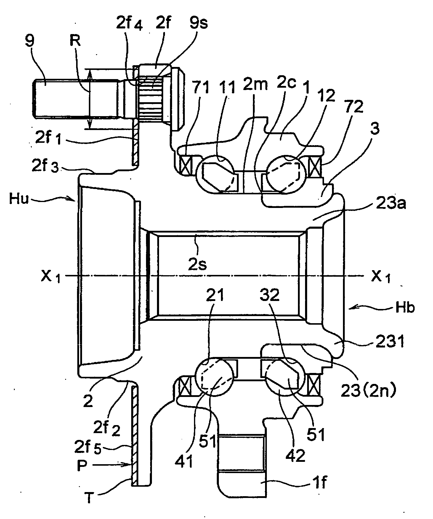
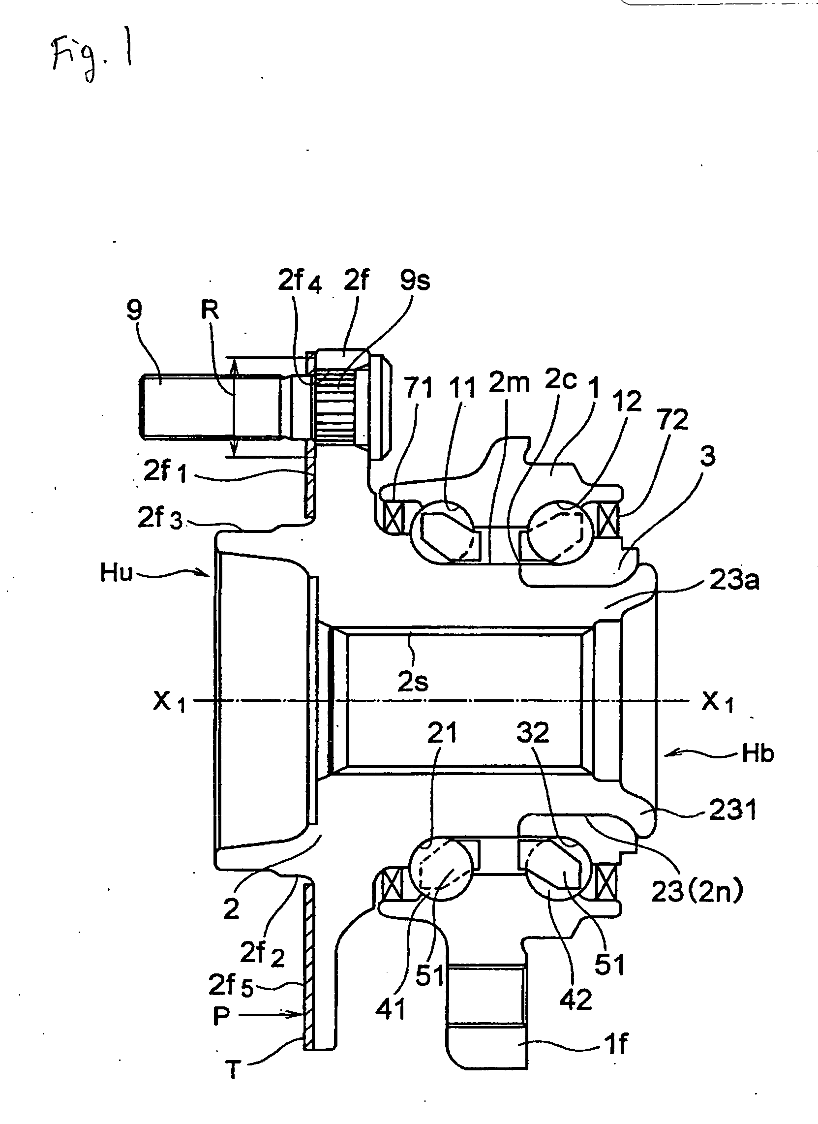
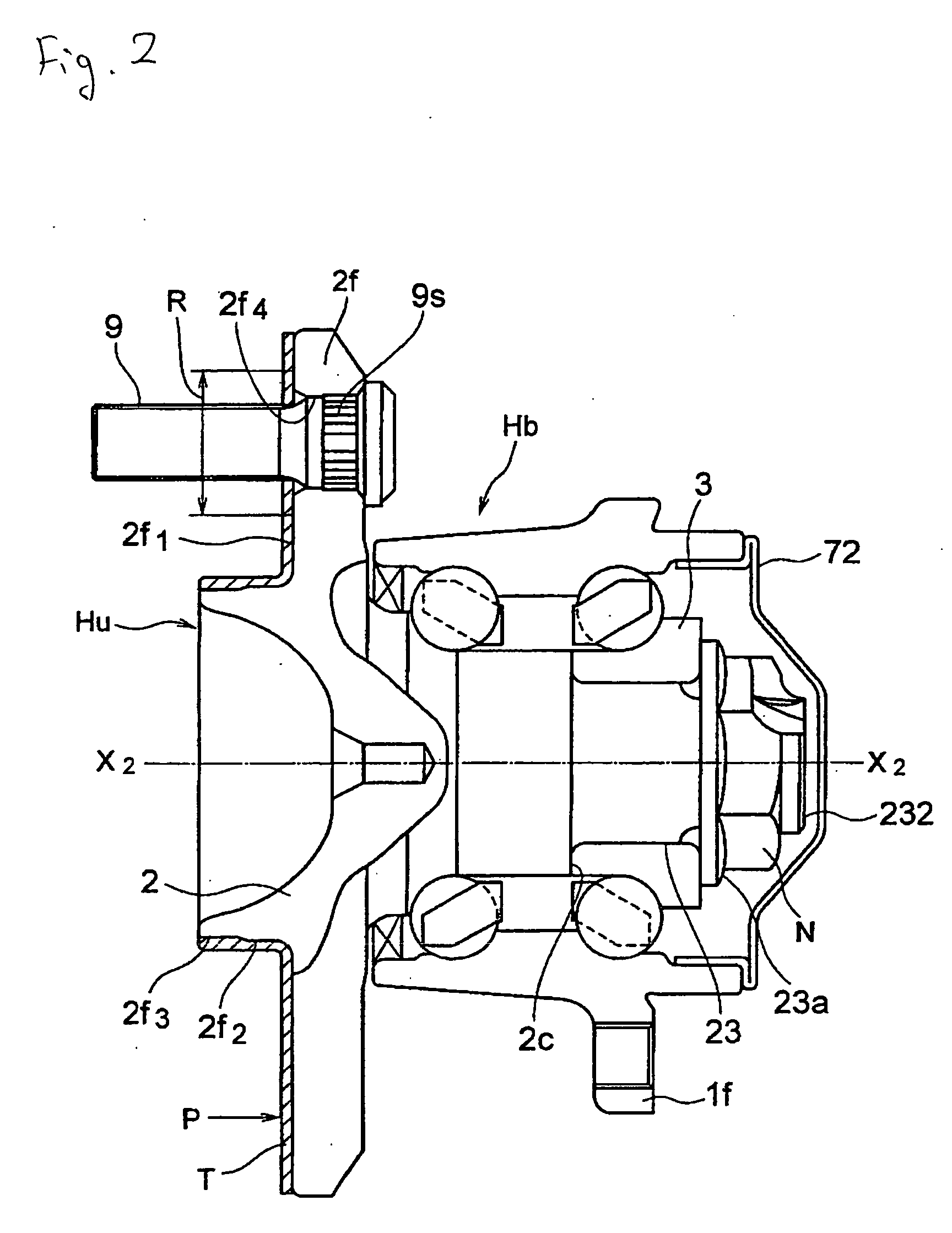
[0043] A hub unit Hu includes an outer ring 1 which has a first inner peripheral raceway 11 at an inner periphery of an outer end-side portion thereof and a second inner peripheral raceway 12 at an inner periphery of a center-side portion thereof, a hub Hb which has a wheel-mounting flange 2f at an outer end-side portion thereof, and has a first outer peripheral raceway 21 (at a portion thereof from the flange 2f toward the center side) opposed to the first inner peripheral raceway 11 of the outer ring 1, and further has a distal end portion 23a at a center-side portion thereof, and has a second inner peripheral raceway 32 opposed to the second inner peripheral raceway 12 of the outer ring 1, balls 41 and 42 interposed respectively between the first inner peripheral raceway of the outer ring 1 and the first outer peripheral raceway of the hub Hb and between the second inner peripheral raceway of the outer ring 1 and the second outer peripheral raceway of the hub Hb, and seals 71 and...


PUM


Abstract

A hub unit includes a double-row outer ring having a first inner peripheral raceway and a second inner peripheral raceway, a hub having a wheel-mounting flange provided with a reference surface for mounting the wheel formed on a vehicle outer end-side thereof, a first outer peripheral raceway opposed to the first inner peripheral raceway of the outer ring, a shaft body and an inner ring element having a second outer peripheral raceway opposed to the second inner peripheral raceway of the outer ring, rolling members interposed between the double-row inner peripheral raceway of the outer ring and the double-row outer peripheral raceway of the hub and cages. A rust-preventive layer is provided at least on the wheel-mounting reference surface of the flange.

Description

[0001] The present invention claims foreign priority to Japanese patent application No. P.2005-32145, filed on Feb. 8, 2005 and P.2005-251879, filed on Aug. 31, 2005, the contents of which is incorporated herein by reference. BACKGROUND OF THE INVENTION [0002] 1. Field of the Invention [0003] This invention relates to a hub unit (wheel-supporting rolling bearing unit) for supporting a wheel of an automobile or the like and a brake rotary member (for example, a brake rotor or a brake drum) rotating with this wheel. [0004] 2. Description of the Background Art [0005] As a hub unit of this kind, there is known one including a hub ring 10, an inner ring 20, an outer ring 30, and a plurality of rolling members 40 as shown in FIG. 5. [0006] A pilot portion 110 and a wheel-mounting flange 120 are provided at an outboard side (which is an outer end portion in a direction of a width of an automobile in a condition in which the hub unit is mounted on the automobile, and means a left end portio...

Claims


Application Information

Patent Timeline
IPC IPC(8): F16C13/00
CPCB60B27/0005B60B27/0084B60B27/0094F16C35/073F16C19/186F16C2326/02
Inventor TAKAHASHI, AKIRAOKU, YOUICHI
Owner NSK LTD
Why Eureka
Try Eureka