Power supply system

Active Publication Date: 2017-01-12
MITSUBISHI ELECTRIC CORP
View PDF5 Cites 12 Cited by
  • Summary
  • Abstract
  • Description
  • Claims
  • Application Information

AI Technical Summary

Benefits of technology

[0014]The power supply system according to the present invention is formed as described above, and thus, the power supply syste

Problems solved by technology

In this way, when any one of the two types of storage devices is adopted, the configuration has unnecessary energy or power, which leads to increases in weight, volume, and cos

Method used


Image

  • Power supply system
  • Power supply system
  • Power supply system

Examples


embodiment 1

[0020]First, a configuration of a power supply system according to the present invention is described with reference to the drawings. Note that, the drawings are schematic and are for the purpose of conceptually illustrating a function, a configuration, or the like. Further, the drawings do not reflect accurate sizes of components illustrated and the like. Unless otherwise specified, a basic configuration of the power supply system is common to all embodiments. Further, like reference numerals are used to designate like or corresponding components throughout the specification.

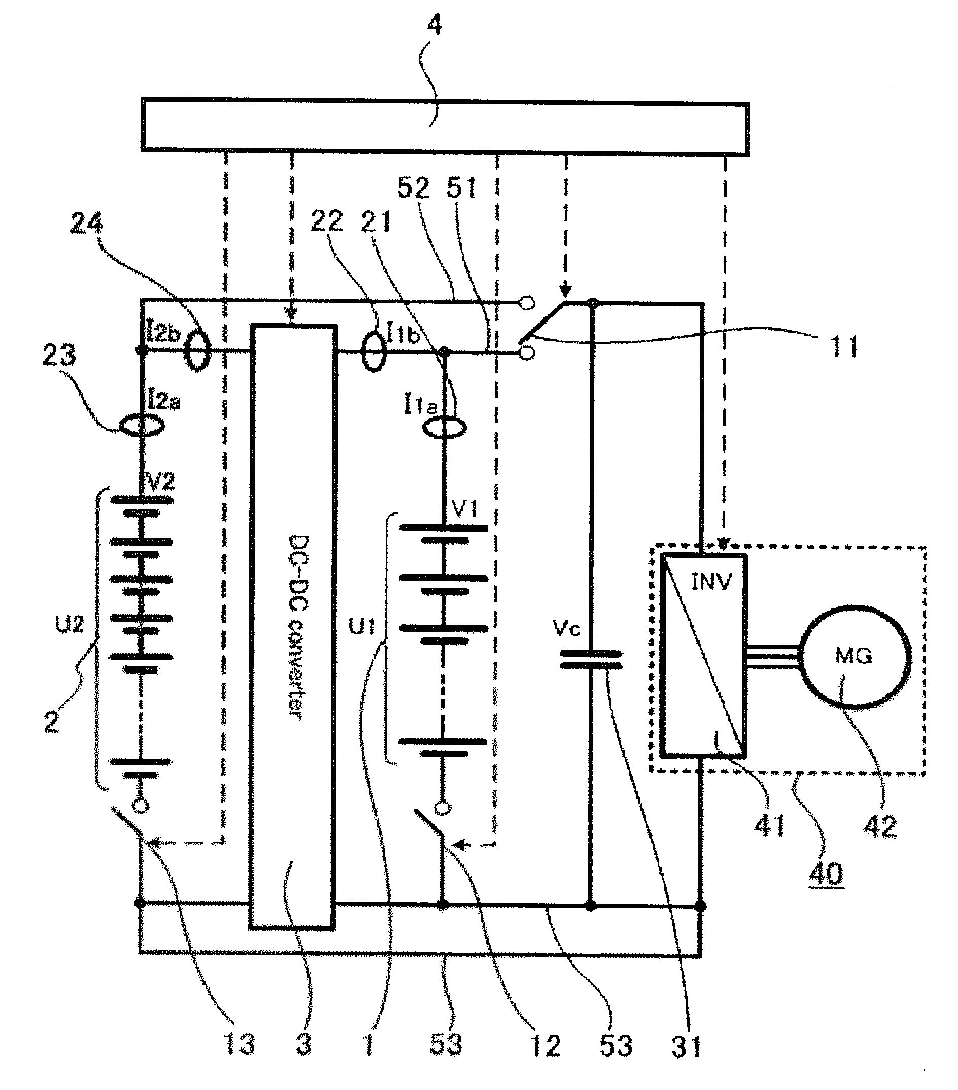
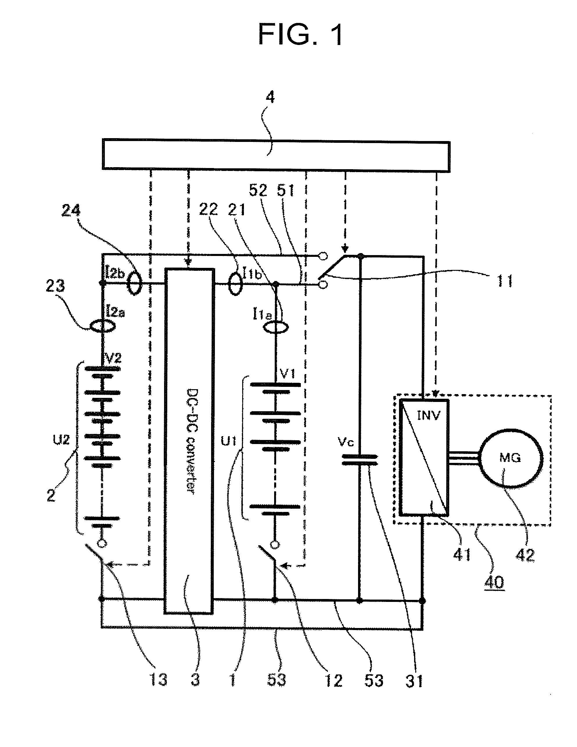
[0021]FIG. 1 is a schematic view for schematically illustrating the configuration of the power supply system according to this embodiment. The power supply system according to this embodiment is described with reference to FIG. 1.

[0022]Note that, in this embodiment, a case in which a motor generator 42 and an inverter 41 are combined as exemplary electric power giving / receiving equipment 40 is described, but as...


PUM


Abstract

In a power supply system using various kinds of storage batteries such as a large capacity storage battery or a small capacity storage battery, an electric power path is complicated, which may increase failures such as a short circuit trouble. There is a problem in that, when a short circuit trouble between storage batteries occurs, damage to a smaller capacity storage battery is serious. Accordingly, in a power supply system according to the present invention, the relationship among voltages, current capacities, and electric power capacities of various kinds of storage batteries such as a large capacity storage battery or a small capacity storage battery is defined so that damage to the storage batteries may be minimized even when malfunction occurs in, for example, switching a switch, and energy transfers from a higher voltage storage device.

Description

TECHNICAL FIELD[0001]The present invention relates to a power supply system. Specifically, the present invention relates to an energy regenerative storage system including a storage device, e.g., a lithium-ion secondary battery, a bidirectional DC-DC converter, and the like.BACKGROUND ART[0002]A lithium-ion secondary battery has been mainly used for portable electronic apparatuses as a lightweight and high-energy density storage device. In recent years, a lithium-ion secondary battery has come to have higher power and has also been adopted for use in large vehicles such as a hybrid automobile and a hybrid rail car. As a tendency in developing a lithium-ion secondary battery, as shown in FIG. 5, the development is becoming bifurcated as follows: development toward a larger capacity and a higher energy density; and development toward a smaller capacity and a higher power density. In applications for a storage device, it is often the case that the peak power is high but only momentary....

Claims


Application Information

Patent Timeline
IPC IPC(8): H02J7/00H02P27/08
CPCH02J7/0024H02J7/0021H02P27/08H01M10/425H01M10/441H01M2220/20Y02E60/10
Inventor TAKEMURA, DAIGOSHIRAGA, SHOWADA, TOSHIHIROYOSHIOKA, SHOJIHARADA, SHIGEKIARAKI, HIROSHIYAMASAKI, HISANORI
Owner MITSUBISHI ELECTRIC CORP
Why Eureka
Try Eureka