Multiple loadlocks and processing chamber

a technology of loading chamber and loadlock, which is applied in the field of loadinglocks, can solve the problems and achieve the effect of limiting the throughput of achievable tools and maximising throughpu

Inactive Publication Date: 2006-08-10
MULTIBEAM SYST
View PDF16 Cites 44 Cited by
  • Summary
  • Abstract
  • Description
  • Claims
  • Application Information

AI Technical Summary

Benefits of technology

[0007] The system can be a vacuum system, in which case it has the advantage of being able to match the loadlock turn-around time (comprising venting, substrate exchange, and pumpdown) to the processing time for one or more large substrates. For example, a vacuum system is used for electron-beam testing for electrical defects of flat panel display (FPD) substrates, wherein a linear array of electron columns simultaneously directs a plurality of electron beams onto the surface of an FPD substrate under test. Each electron beam is used to test the electrical functionality of individual pixels within the displays being manufactured on the substrate. Typically, the testing time for a Gen-8 LCD substrate is 40 s when employing a multiple column assembly 104 (see FIG. 1), as disclosed in U.S. Provisional Patent Application No. 60 / 608,609. Combined with substrate insertion and removal from the processing chamber 102 where electrical testing of the substrate is performed, the total time to test an LCD substrate may be 60 s. If the loadlock vent, substrate exchange and pumpdown process can be performed in parallel with substrate electrical testing, then the maximum throughput can be achieved. Throughput is the inverse of the turn around cycle time (TACT), where a 60 s TACT corresponds to 60 substrates / hour, while a 120 s TACT gives only 30 substrates / hour. The difficulty generally encountered in doing the loadlock vent, exchange and pumpdown cycle in parallel with electrical testing is that the total time for this cycle can exceed 60 s, thereby limiting the achievable tool throughput.

Problems solved by technology

The difficulty generally encountered in doing the loadlock vent, exchange and pumpdown cycle in parallel with electrical testing is that the total time for this cycle can exceed 60 s, thereby limiting the achievable tool throughput.

Method used


Image

  • Multiple loadlocks and processing chamber
  • Multiple loadlocks and processing chamber
  • Multiple loadlocks and processing chamber

Examples


first embodiment

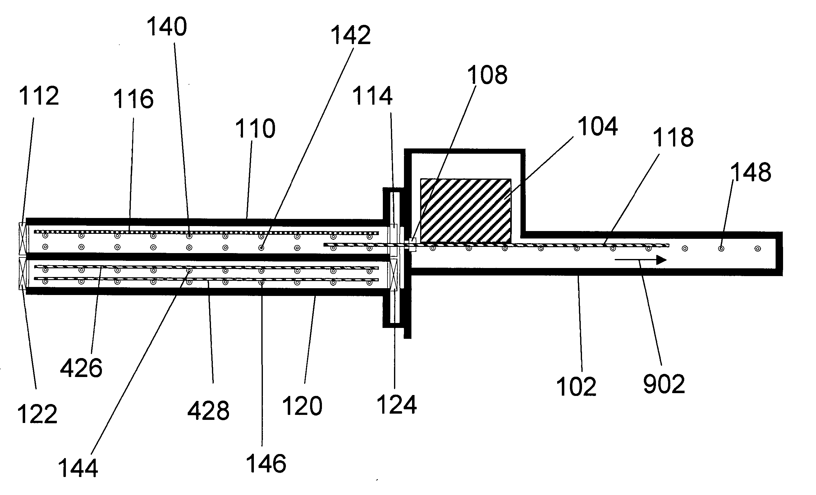
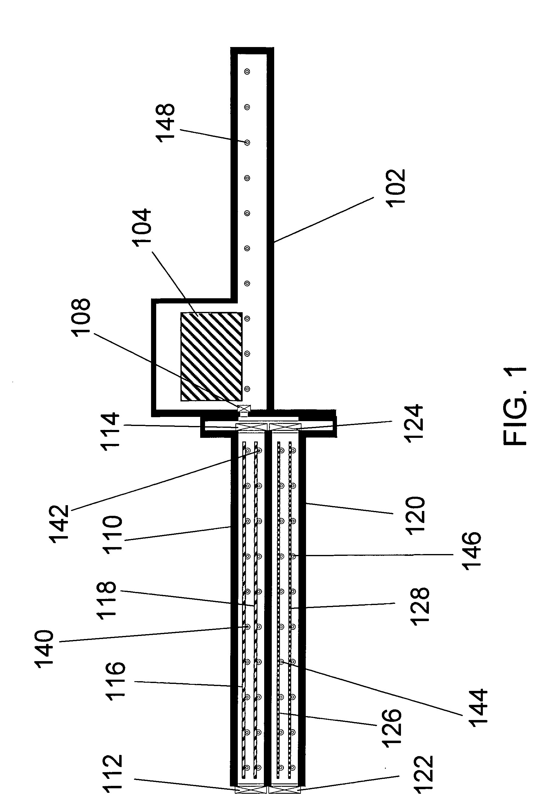
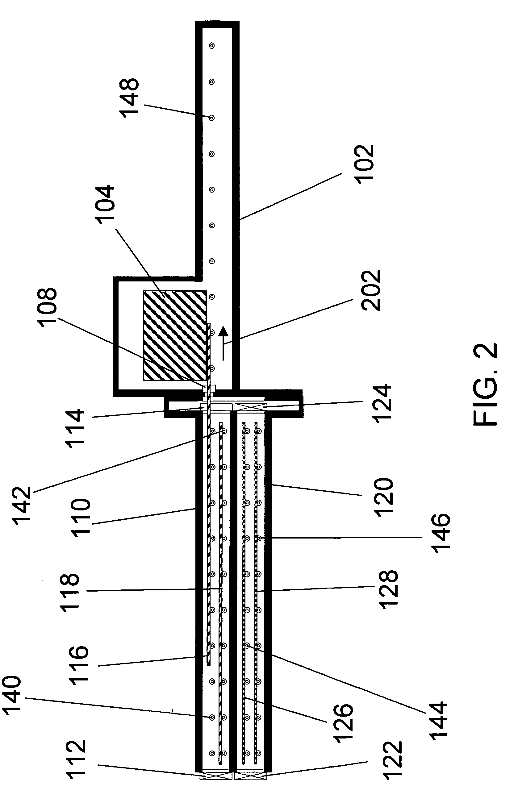
[0051]FIGS. 1 through 18 show cross-sectional schematic views of the present invention comprising dual loadlocks and a processing chamber. The vacuum system is illustrated at various times in the operational cycle. During the operational cycle shown here, a total of four substrates 116, 118, 426, and 428 are tested using electron beams generated by the column assembly 104, mounted in the processing chamber 102. At the left of processing chamber 102 in FIGS. 1 through 18 is the loadlock assembly, comprising loadlock chambers #1 110 and #2 120, external valves 112 and 122, internal valves 114 and 124, and rollers 140, 142, 144, and 146.

[0052] Substrates located outside the vacuum system are inserted into or removed from loadlock chamber #1 110 through external valve 112. Substrates located in loadlock chamber #1 110 are inserted into or removed from processing chamber 102 through internal valve 114. Substrates being inserted into or removed from the upper slot of loadlock chamber #1 1...

second embodiment

Similar feedpaths can be defined for the present invention, for example, the feedpath for substrate 2118 in FIGS. 21-23 includes the following positions: [0120] 1. Lower slot of input loadlock chamber #1 2110[0121] 2. Processing chamber 2104[0122] 3. Lower slot of output loadlock chamber #1 2210

[0123] The loadlock chambers 2110 and 2120 are assumed to be connected to pumping and venting manifolds, as is familiar to those skilled in the art. Venting systems typically consist of a number of valves, manifolds, and a supply of dry nitrogen—the same venting system can be used for both input loadlock chambers 2110 and 2120, since only one of the input loadlock chambers 2110 and 2120 is venting at any one time. Pumpdown systems typically consist of a number of valves, manifolds, and pumps such as air ejectors, mechanical pumps, turbopumps, and / or cryopumps—the same pumping system can be used for both input loadlock chambers 2110 and 2120, since only one of the input loadlock chambers 2110 ...


PUM


Abstract

A system for the processing of large substrates such as those employed in the manufacture of flat panel displays is disclosed. In a first embodiment, a loadlock assembly, comprising two loadlock chambers configured to accommodate a multiplicity of large substrates, is coupled to a processing chamber with an input/output port. The processing chamber and the loadlock assembly are configured to move relative to each other to allow positioning of: either of the two loadlock chambers with said port; and any one of the multiplicity of large substrates for passage through the port. In a second embodiment, input and output loadlock assemblies, each comprising two loadlock chambers, are coupled to a dual-ported processing chamber in a pass-through configuration, wherein the input and output loadlock assemblies each move independently relative to the processing chamber.

Description

BACKGROUND OF THE INVENTION [0001] 1. Fields of Use for the Invention [0002] This invention relates to the field of systems for the processing of large substrates such as those used in the manufacture of flat panel displays, and in particular to loadlocks. [0003] 2. Description of the Related Art [0004] During the manufacture of flat panel displays, such as liquid crystal displays (LCDs), for many early steps, the circuitry for the displays is formed on the surface of a large substrate, often containing six or more displays in progress. Typically, many of the manufacturing steps for LCDs require the use of vacuum processing. Due to the large sizes of the LCD substrates during manufacture (>2 m×2 m), correspondingly large vacuum systems are required. A common method for introducing substrates into a vacuum system is the use of “loadlocks”, which are additional chambers (one or more) attached to the main processing chamber. The loadlocks have two valves, one which opens to allow in...

Claims


Application Information

Patent Timeline
Patent Type & Authority Applications(United States)
IPC IPC(8): B65G1/00
CPCH01L21/67201H01L21/67236
Inventor PARKER, N. WILLIAMMILLER, S. DANIELRAVI, TIRUNELVELI S.
Owner MULTIBEAM SYST
Why Eureka
Try Eureka