
Advanced control system for enhanced operation of oscillating combustion in combustors

a control system and advanced technology, applied in the direction of combustion types, combustion using lumps and pulverizing fuel, lighting and heating apparatus, etc., can solve the problems of complex operation on top of controlling the additional oxidant flow, frequent shut-down and start-up

Inactive Publication Date: 2006-08-10
VARAGANI RAJANI K +2
View PDF10 Cites 40 Cited by
  • Summary
  • Abstract
  • Description
  • Claims
  • Application Information

AI Technical Summary

Benefits of technology

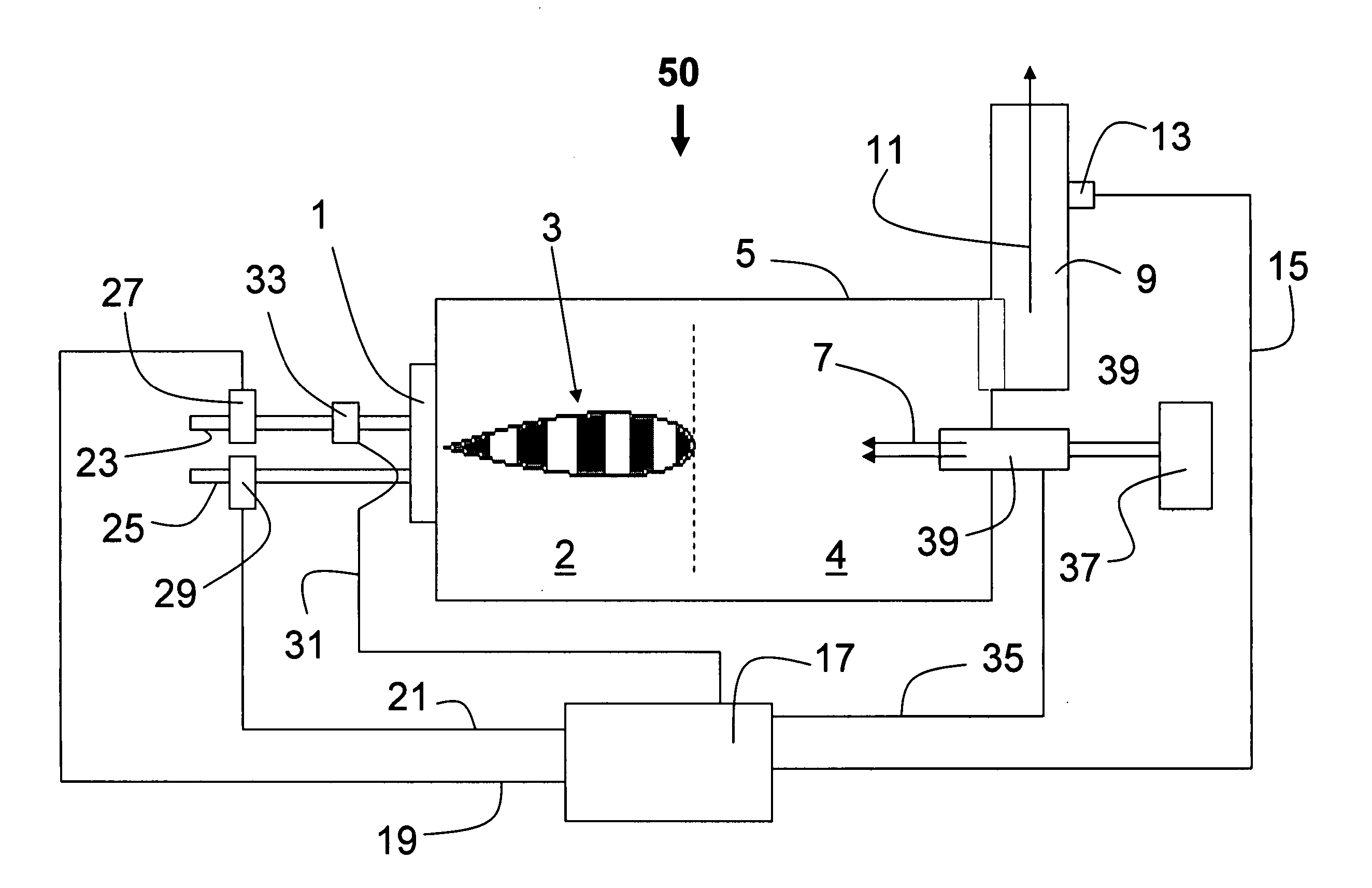
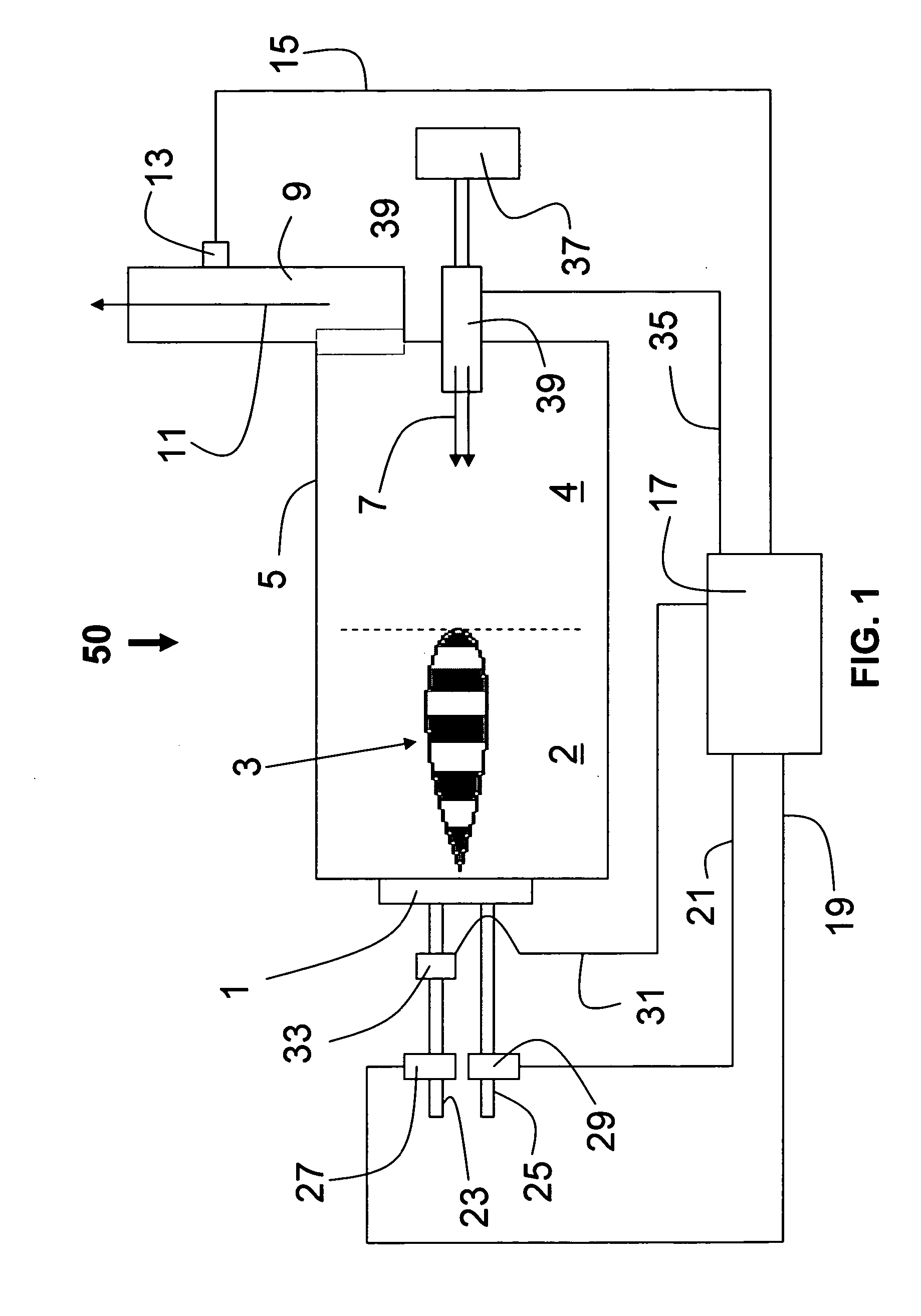
[0007] A process for optimizing levels of NOx and CO during fuel combustion is performed and includes the steps of a flow of a fuel to a burner is supplied, and flow of a main oxidant is supplied to a burner. The flow rate of the main oxidant is controlled by a main oxidant flow rate control unit. Oscillating combustion is generated by oscillating the fuel flow with an oscillating valve and combusting the oscillating fuel with the main oxidant adjacent the burner to produce combustion products. A post-combustion oxidant is injected into the combustion products. The injection rate of the post-combustion oxidant injection being is controlled by a post-combustion oxidant flow rate control unit. The combustion products and the injected post-combustion oxid

Problems solved by technology

In most cases, these proposed processes are running at varying loads without human / operator intervention, and are subject to frequent shut-downs and start-ups.
This complicates the operation on top of controlling the additional oxidant flow.
Many problems arise from the implementation of the oscillating combustion technology in these types of processes.

Method used


Image

  • Advanced control system for enhanced operation of oscillating combustion in combustors
  • Advanced control system for enhanced operation of oscillating combustion in combustors
  • Advanced control system for enhanced operation of oscillating combustion in combustors

Examples


Embodiment Construction

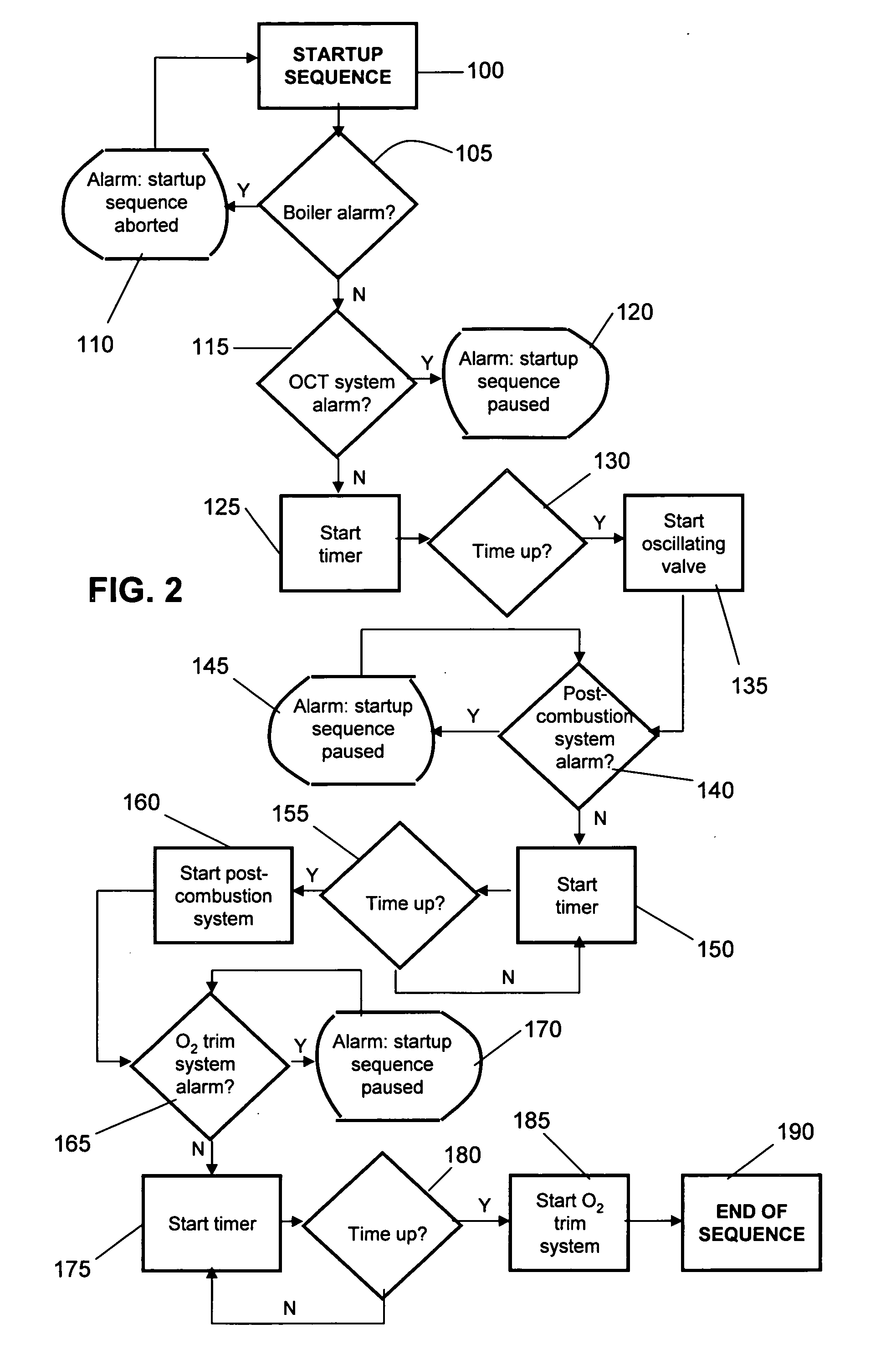
[0024] In order to solve the above mentioned problems, the present invention proposes an innovative system and method for operating and controlling the oscillating combustion technology in combustors subject to demanding operating constraints, such as industrial boilers and process heaters. An improvement of the present invention is directed to performing safe startups and shutdowns with a controller. One purpose is to integrate an innovative oscillating combustion control scheme to the existing process in order to allow a safe operation of this process at any time and / or to adjust the various control parameters in order to maintain optimal or satisfactory NOx (and optionally CO) reduction and process efficiency.

[0025] The proposed invention can be applied to any industrial application involving the use of at least one burner utilizing oscillating combustion, but is more especially suited for industrial boilers and process heaters utilizing oscillating combustion. Suitable oscillat...


PUM


Abstract

Methods for optimizing emission levels from combustion operations, which include a system and process for optimizing levels of NOx and CO during fuel combustion including supplying flows of fuel (which is predetermined) and main oxidant to a burner. Oscillating combustion is generated by oscillating the fuel flow with an oscillating valve and combusting the oscillating fuel with the main oxidant adjacent the burner to produce combustion products. A post-combustion oxidant is injected into the combustion products where it is combusted with the combustion products. A controller is operatively associated with control units for controlling the main oxidant and post-combustion oxidant flow rates and the oscillating valve.

Description

CROSS-REFERENCE TO RELATED APPLICATIONS [0001] This application claims benefit under 35 U.S.C. § 119(e) to provisional application No. 60 / 635,737, filed Dec. 13, 2004, the entire contents of which are incorporated herein by reference.RELATED ART [0002] The concept of oscillating combustion is a recognized technology for the reduction of NOx in industrial furnaces. The principle and the various methods of implementation are broadly described in U.S. Pat. No. 4,846,665, U.S. Pat. No. 5,302,111, and U.S. Pat. No. 5,522,721. The main idea is to pulse the flow of fuel, or air being supplied to at least one burner of the furnace, to generate successive fuel-rich and fuel-lean zones in a flame; thereby, reducing NOx emissions. [0003] The inventors are only aware of oscillating combustion's commercial implementation in large multi-fired industrial furnaces, such as glass and steel reheating furnaces. In these processes, integration of oscillating combustion to the furnace is relatively easy...

Claims


Application Information

Patent Timeline
IPC IPC(8): F23N1/02
CPCF23C9/08F23K2900/05003F23N1/022F23N5/006F23N2027/02F23N2227/02
Inventor VARAGANI, RAJANI K.PENFORNIS, ERWINGERMOUNI, OMAR
Owner VARAGANI RAJANI K
Learn More