Vehicle collision warning system

a technology for collision warning and vehicles, applied in vehicle position/course/altitude control, using reradiation, instruments, etc., can solve the problems of difficult distance measurement, and the warning system does not necessarily determine the actual distance to a remote object, so as to facilitate the avoidance of a vehicle collision and accurate time to collision

Inactive Publication Date: 2006-08-10
TOYOTA MOTOR CO LTD
View PDF15 Cites 75 Cited by
  • Summary
  • Abstract
  • Description
  • Claims
  • Application Information

AI Technical Summary

Benefits of technology

[0006] The image analyzer performs an optical flow analysis of the image data, and determines an optical flow vector for image elements within the image. The possibility of a collision is determined by the location of any focus of expansion relative to the optical flow of an image element, as described in more detail below. The focus of expansion is a point from which optical flow vectors appear to diverge, and is correlated with the vehicle direction.
[0007] A method of facilitating avoidance of a vehicle collision with an object comprises providing at least one vision sensor providing a wide field of view of the vehicle surroundings, obtaining time-sequential image data of the vehic...

Problems solved by technology

However, such distance measurements may be difficult in changing environmental conditions.
Hence, an...

Method used


Image

  • Vehicle collision warning system
  • Vehicle collision warning system
  • Vehicle collision warning system

Examples


Embodiment Construction

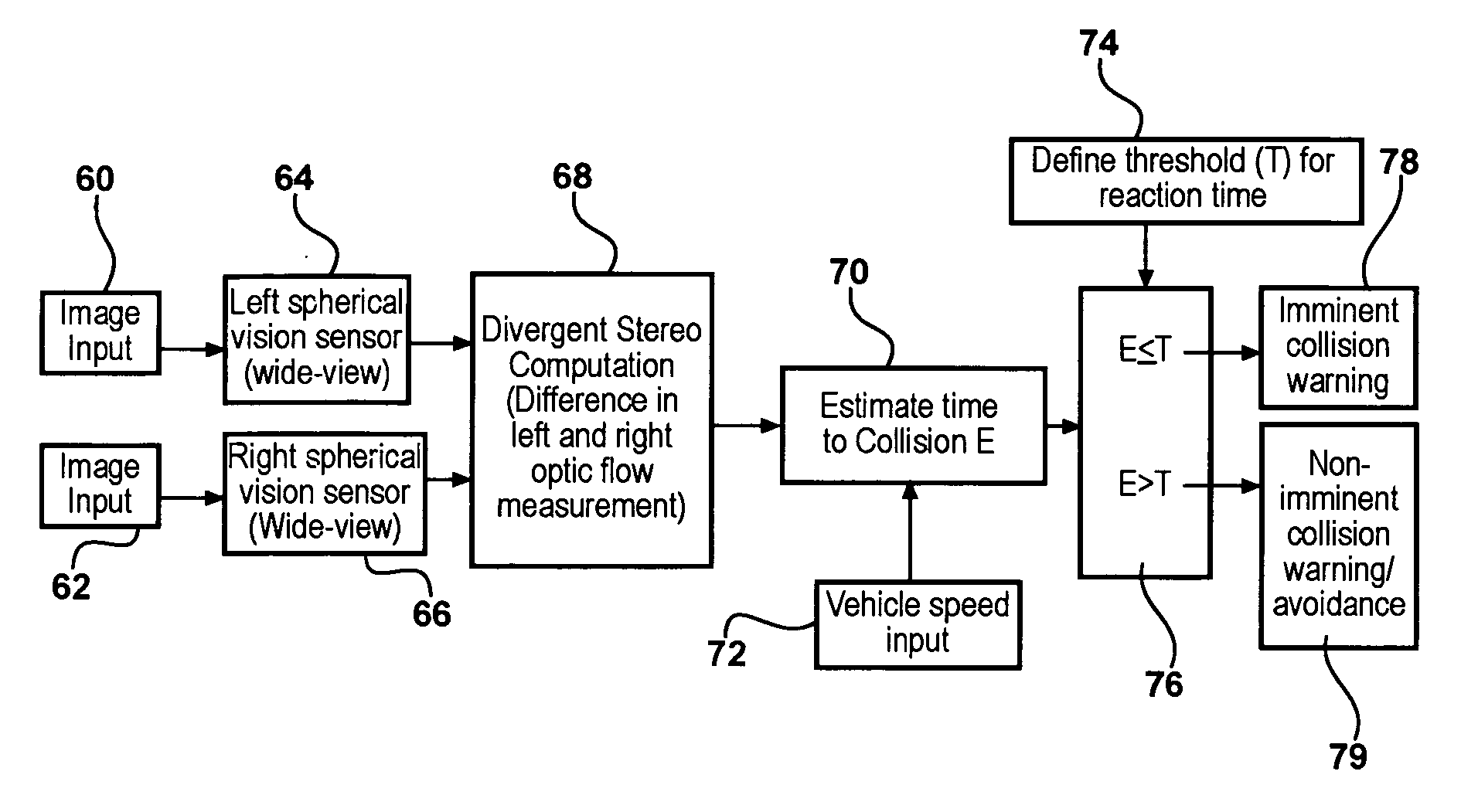
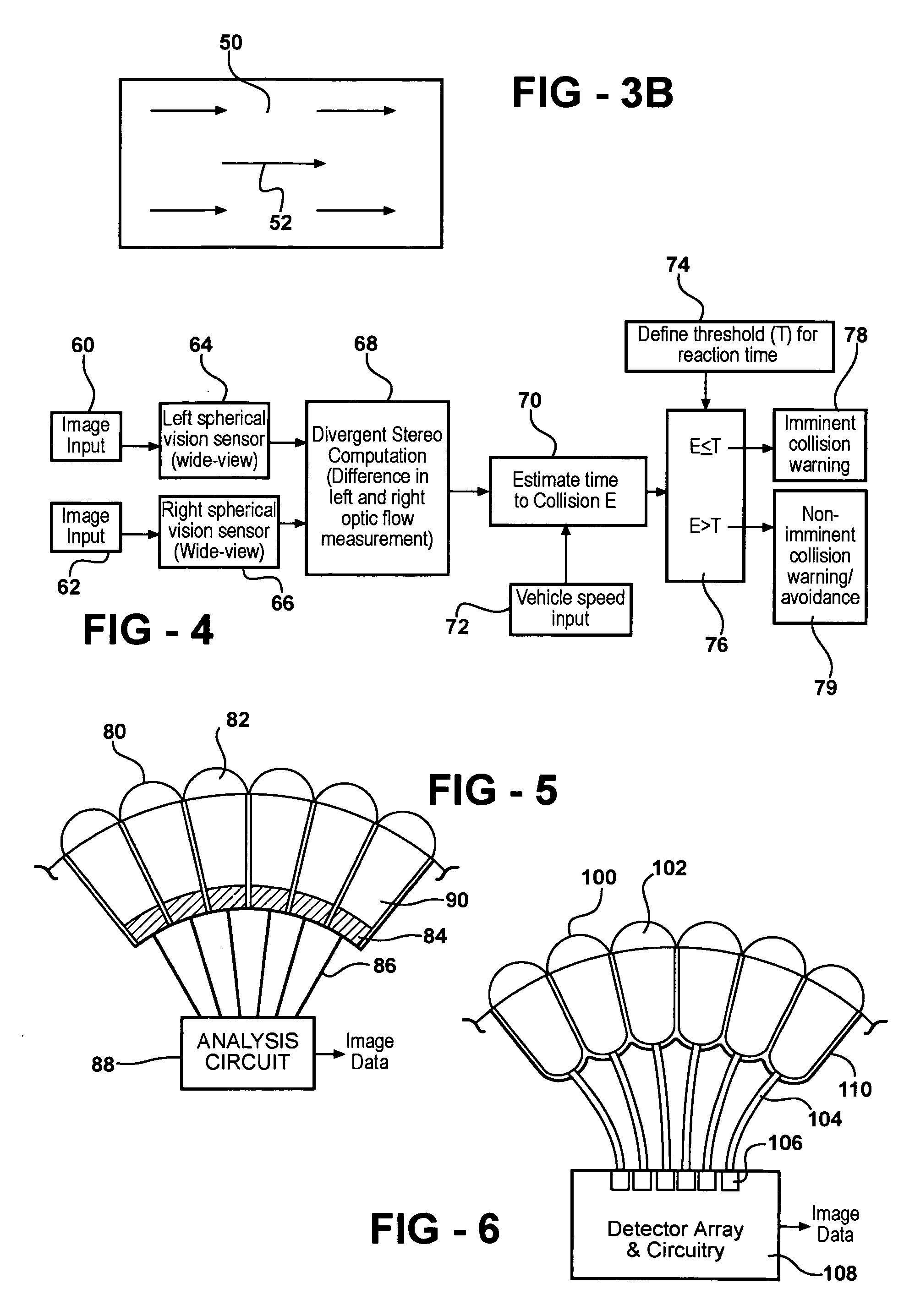
[0022] An improved apparatus for collision avoidance comprises one or more vision sensors providing image data, and an image analyzer. The image data contains an image element corresponding to an object in the path of the vehicle. The image analyzer provides an estimated time to collision of the vehicle with the object, and initiates a collision avoidance response, for example an audible or visual warning provided to the vehicle operator.

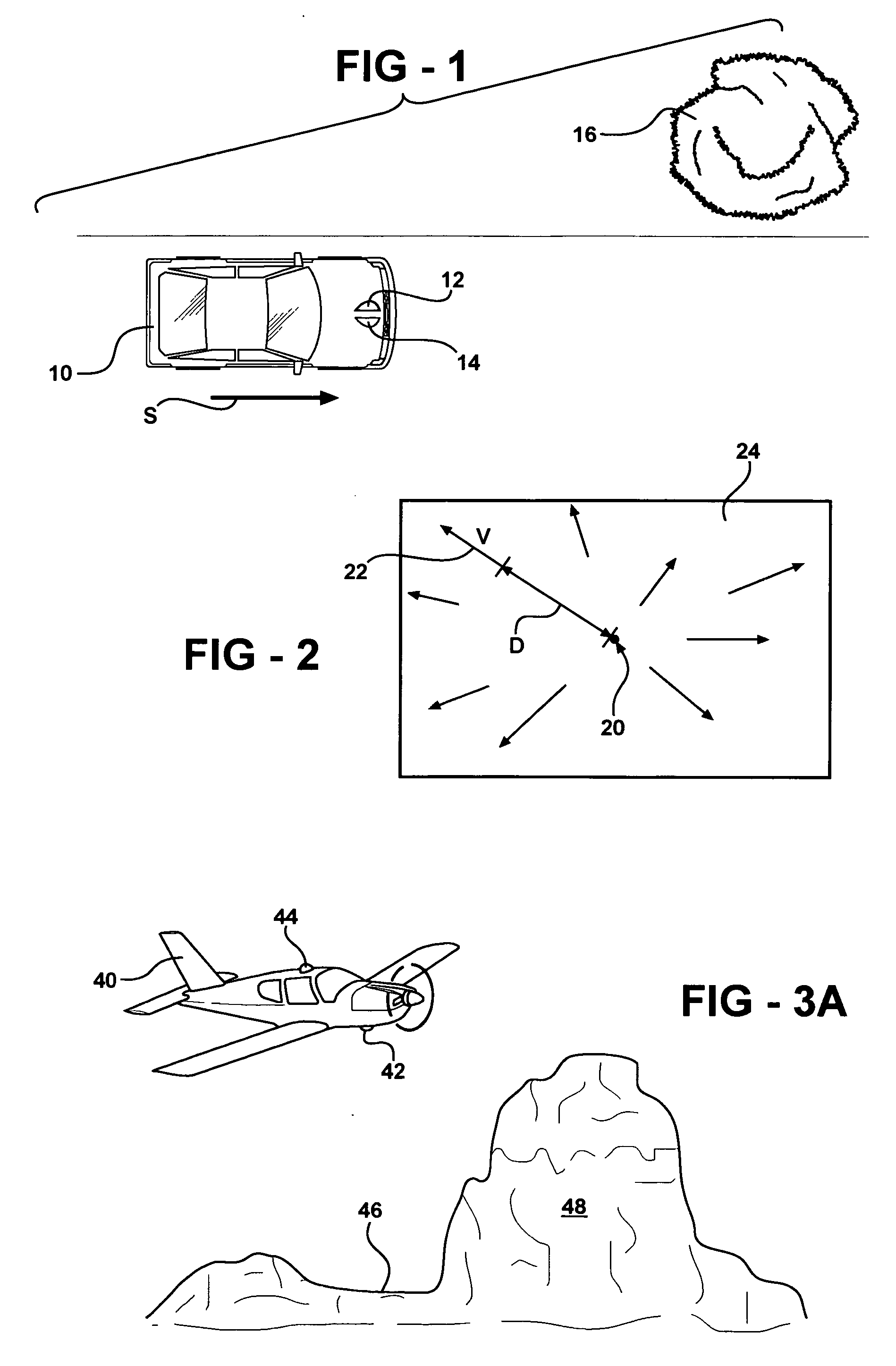
[0023] The estimated time to collision is determined from a rate of expansion of the image element within the image data, for example using optical flow analysis of the image data.

[0024] In examples of the invention, two vision sensors are used, each having a wide field of view, such as a semicircular or hemispherical field of view. The two vision sensors are located so as to face in opposite directions, or otherwise widely diverging directions. The two vision sensors hence can hence provide an all-around view. This is in contrast with conventiona...


PUM


Abstract

An apparatus for facilitating avoidance of a vehicle collision with an object, comprises a vision sensor providing image data, and an image analyzer, operable to provide an estimated time to collision of the vehicle with the object. The estimated time to collision is determined from a rate of expansion of an image element corresponding to the object within the image data, and the apparatus provides a warning if the estimated time to collision is less than or approximately equal to a predetermined time.

Description

FIELD OF THE INVENTION [0001] The invention relates to collision warning methods and apparatus for vehicles. BACKGROUND OF THE INVENTION [0002] Optical flow is a measure of image movement across a visual field. It is the apparent motion of image brightness patterns in a sequence of images. In an image each pixel corresponds to the value obtained by the projection of a three-dimensional image onto an image plane. When an object moves, the corresponding projection, or image element within the image data corresponding to object, changes position in the image plane. Optical flow is the vector field showing the direction and magnitude of such changes from one image to the other. [0003] In conventional stereo vision based collision avoidance approaches, the actual distance to a remote object is calculated. However, such distance measurements may be difficult in changing environmental conditions. Hence, an improved collision warning system would not necessarily determine the actual distanc...

Claims


Application Information

Patent Timeline
IPC IPC(8): G01S1/00
CPCG01S11/12
Inventor SHERONY, RINI
Owner TOYOTA MOTOR CO LTD
Why Eureka
Try Eureka