
System and method for memory hub-based expansion bus

a memory hub and expansion bus technology, applied in the field of memory system for processor-based computing systems, can solve the problems of reducing the hardware limitation of the memory device itself, affecting the performance of the memory device, and not related to the bandwidth limitation, etc., and reducing the hardware limitation adds cost, power, and/or size to the memory

Inactive Publication Date: 2006-08-10
ROUND ROCK RES LLC
View PDF33 Cites 77 Cited by
  • Summary
  • Abstract
  • Description
  • Claims
  • Application Information

AI Technical Summary

Benefits of technology

This architecture reduces memory request and response bottlenecks, allows for efficient memory access by multiple components, and maintains signal integrity, thereby improving overall system performance and reducing costs by distributing memory access loads across multiple memory modules.

Problems solved by technology

Generally, bandwidth limitations are not related to the memory controllers since the memory controllers sequence data to and from the system memory as fast as the memory devices allow.
One reason for the non-linear relationship between data bus speed and bandwidth is the hardware limitations within the memory devices themselves.
Although these hardware limitations can be reduced to some degree through the design of the memory device, a compromise must be made because reducing the hardware limitations typically adds cost, power, and / or size to the memory devices, all of which are undesirable alternatives.
Thus, given these constraints, although it is easy for memory devices to move “well-behaved” traffic at ever increasing rates, for example, sequel traffic to the same page of a memory device, it is much more difficult for the memory devices to resolve “badly-behaved traffic,” such as bouncing between different pages or banks of the memory device.
As a result, the increase in memory data bus bandwidth does not yield a corresponding increase in information bandwidth.
In addition to the limited bandwidth between processors and memory devices, the performance of computer systems is also limited by latency problems that increase the time required to read data from system memory devices.
Therefore, although SDRAM devices can synchronously output burst data at a high data rate, the delay in initially providing the data can significantly slow the operating speed of a computer system using such SDRAM devices.
However, as with bandwidth, the increase in memory data bus speeds do not yield a linear reduction of latency, for essentially the same reasons previously discussed.
Although increasing memory data bus speed has, to some degree, been successful in increasing bandwidth and reducing latency, other issues are raised by this approach.
The effectiveness of these conventional approaches are, however, limited.
However, when only one memory module can be plugged in per interface, it becomes too costly to add a separate memory interface for each memory slot.
In other words, it pushes the system controllers package out of the commodity range and into the boutique range, thereby, greatly adding cost.

Method used


Image

  • System and method for memory hub-based expansion bus
  • System and method for memory hub-based expansion bus
  • System and method for memory hub-based expansion bus

Examples


Embodiment Construction

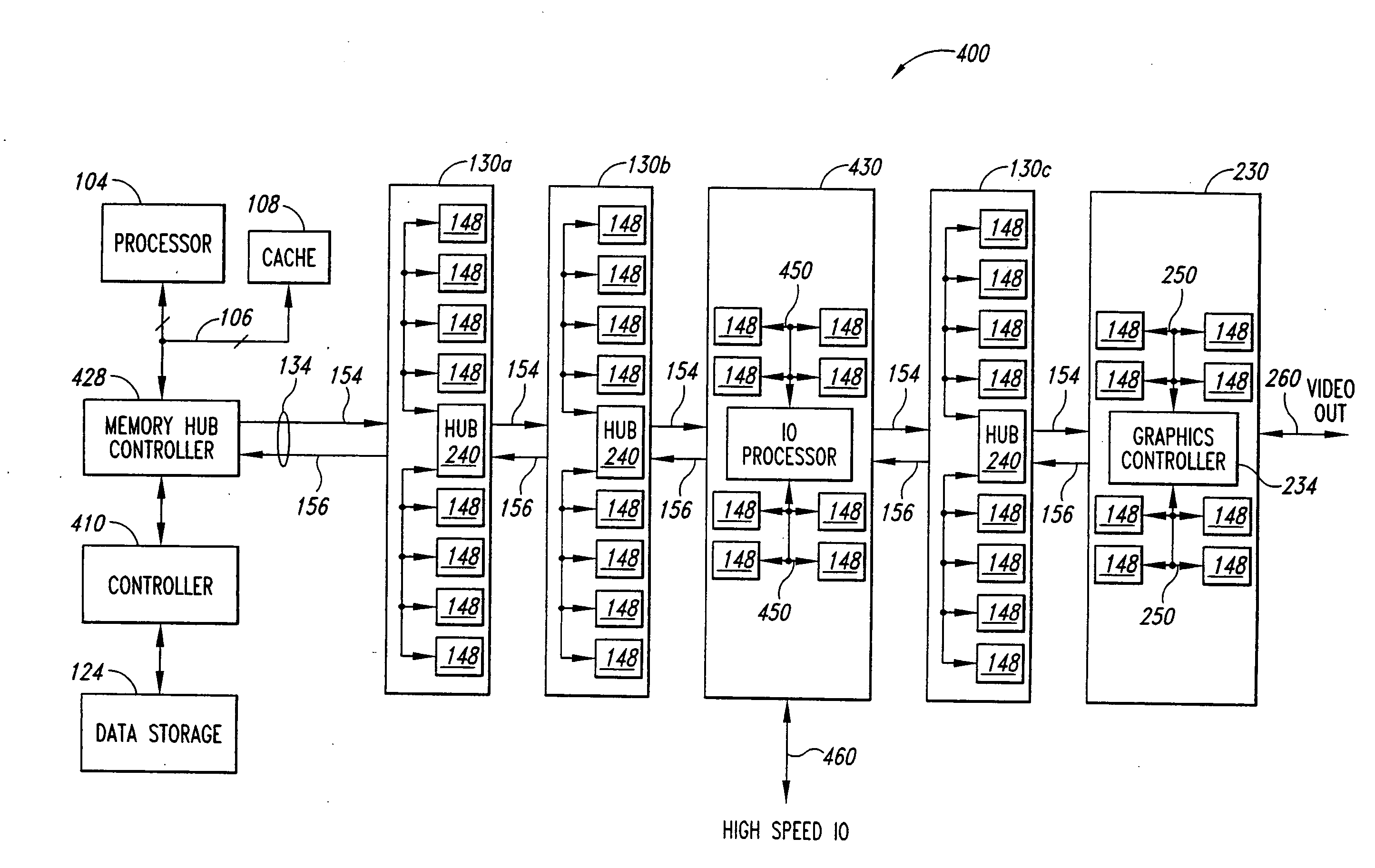
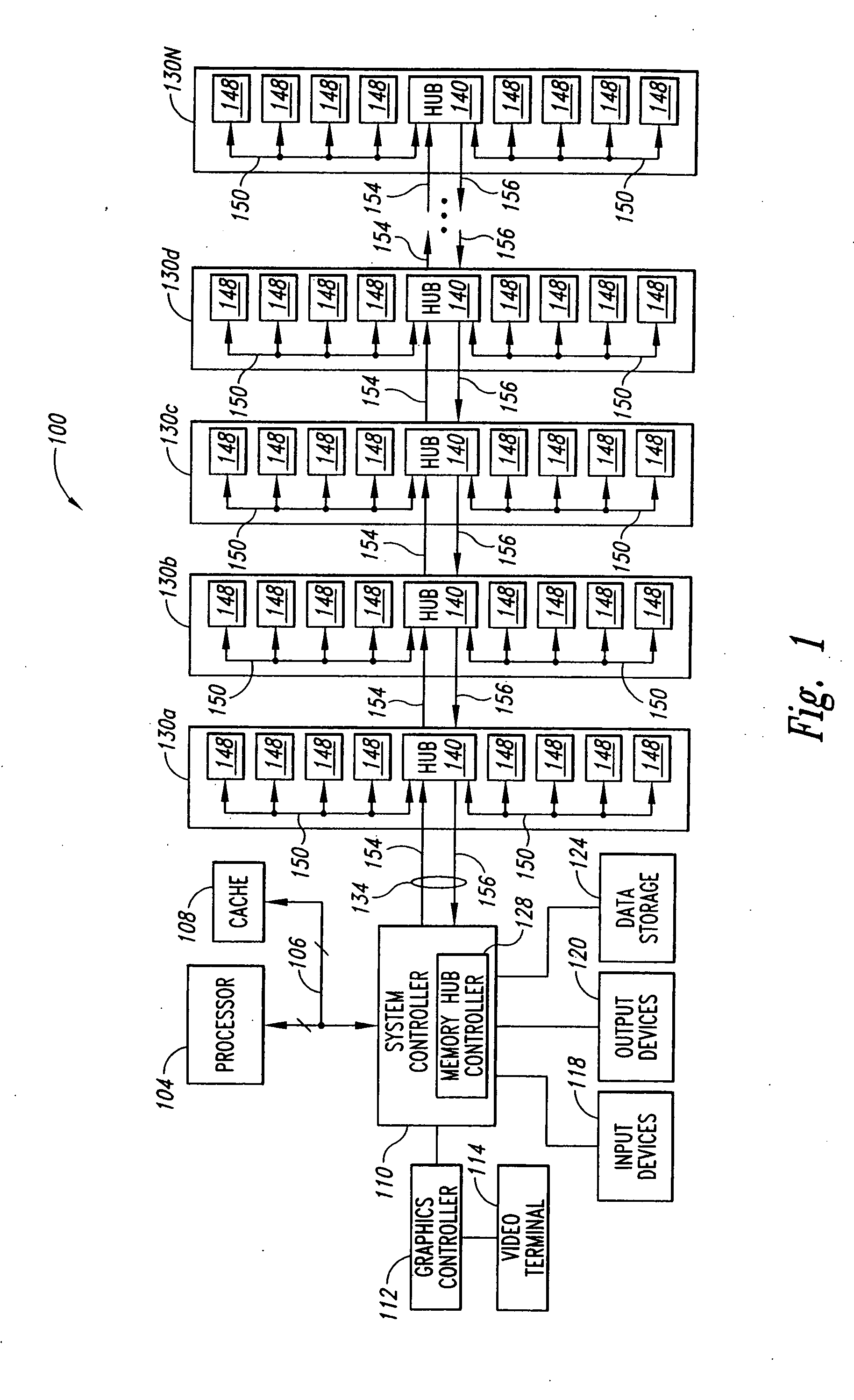
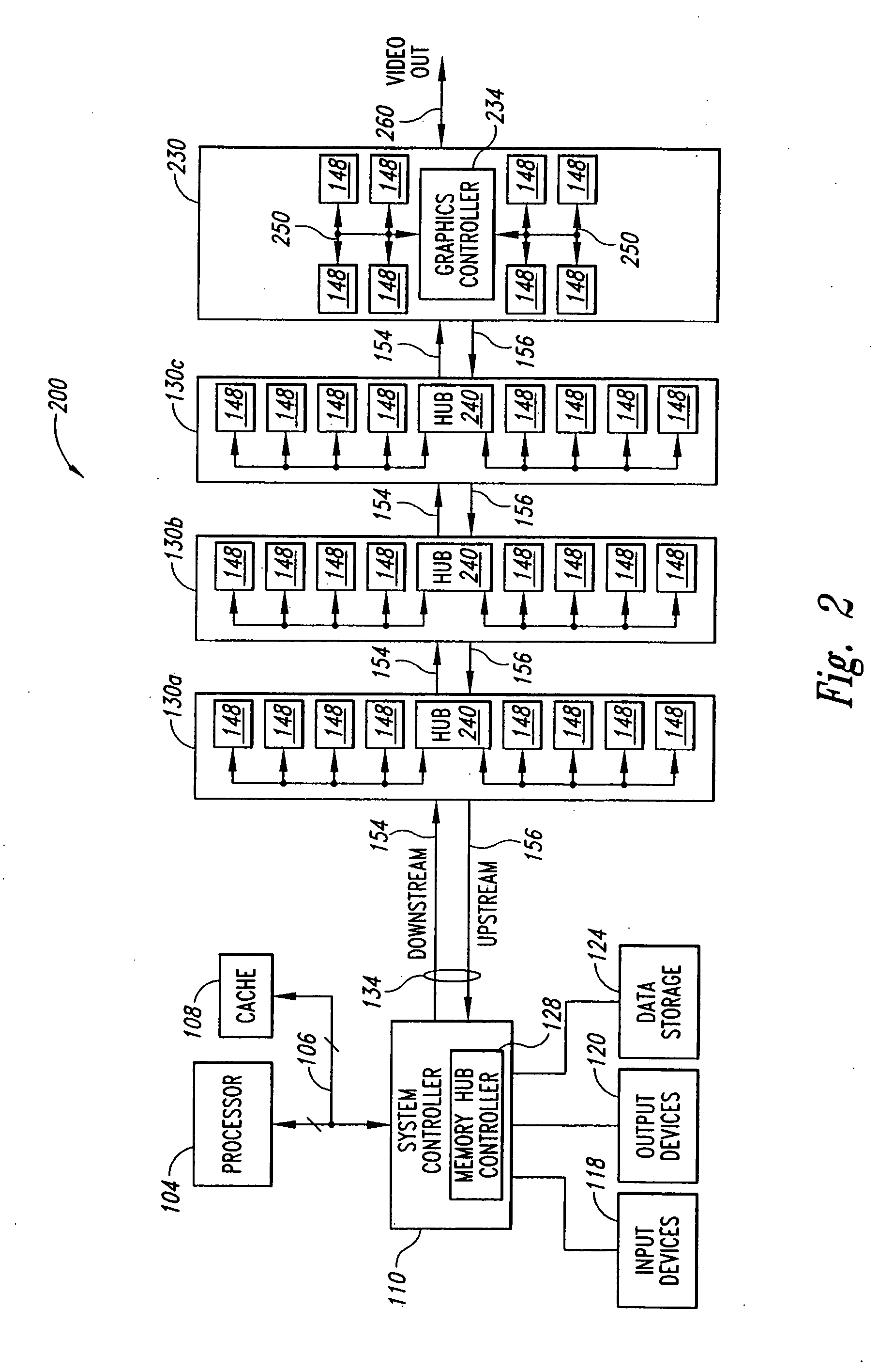
[0016]FIG. 2 illustrates a processor based computing system 200 according to an embodiment of the present invention. The system 200 includes many of the same functional blocks as previously described with reference to FIG. 1. As such, the same reference numbers will be used in FIG. 2 as in FIG. 1 to refer to the same functional blocks where appropriate. The system 200 includes a processor 104 coupled to a system controller 110 through a processor bus 106. As in FIG. 1, the processor performs various computing functions, for example, executing software to perform specific calculations or tasks, and the processor bus 106 typically includes an address bus, a control bus, and a data bus. A cache memory 108 is also coupled to the processor bus 106 to provide the processor 104 with temporary storage of frequently used data and instructions. As previously discussed with respect to FIG. 1, the system controller 110 serves as a communications path to the processor 104 for a variety of other ...


PUM


Abstract

A system memory includes a memory hub controller, a memory module accessible by the memory hub controller, and an expansion module having a processor circuit coupled to the memory module and also having access to the memory module. The memory hub controller is coupled to the memory hub through a first portion of a memory bus on which the memory requests from the memory hub controller and memory responses from the memory hub are coupled. A second portion of the memory bus couples the memory hub to the processor circuit and is used to couple memory requests from the processor circuit and memory responses provided by the memory hub to the processor circuit.

Description

TECHNICAL FIELD [0001] The present invention relates generally to a memory system for a processor-based computing system, and more particularly, to a hub-based memory system providing expansion capabilities for computer components. BACKGROUND OF THE INVENTION [0002] Computer systems use memory devices, such as dynamic random access memory (“DRAM”) devices, to store data that are accessed by a processor. These memory devices are normally used as system memory in a computer system. In a typical computer system, the processor communicates with the system memory through a processor bus and a memory controller. The memory devices of the system memory, typically arranged in memory modules having multiple memory devices, are coupled through a memory bus to the memory controller. The processor issues a memory request, which includes a memory command, such as a read command, and an address designating the location from which data or instructions are to be read. The memory controller uses the...

Claims


Application Information

Patent Timeline
Patent Type & Authority Applications(United States)
IPC IPC(8): G06F12/14G06F13/36G06F13/42
CPCG06F13/4022G06F13/4234G06F13/4247Y10S370/912
Inventor JEDDELOH, JOSEPH M.
Owner ROUND ROCK RES LLC
Learn More