Microtome

a microtome and microtome technology, applied in the field of microtomes, can solve the problems of affecting the quality of the finished object, the inability to completely avoid the deformation of the processed object and the thin slice which has been cut off, and the cost of freezing the processed obj

Inactive Publication Date: 2006-08-17
ROWIAK GMBH
View PDF24 Cites 78 Cited by
  • Summary
  • Abstract
  • Description
  • Claims
  • Application Information

AI Technical Summary

Benefits of technology

[0011] The object of the invention is to make available a microtome and a process for microtomy which enables careful microtomy of the processed object.

Problems solved by technology

The disadvantage in this process is that the so-called frozen sections which have been obtained from frozen processed objects generally do not show many details of the processed object and moreover artifacts are produced in the processed object by freezing.
Another disadvantage of freezing is that deformation of the processed object and of the thin slice which has been cut off cannot be completely avoided by freezing.
Moreover, the freezing of the processed object requires additional cost; this prevents prompt preparation of slices which can be viewed under a microscope and makes preparation altogether expensive.
Embedding or impregnation with an embedding material is more time-consuming and complex with respect to the process engineering effort than freezing of the processed object.
Embedding or impregnation often causes a change of the processed object so that upon later study of the slices obtained, artifacts are observed.
In this prior microtomy the above described disadvantages occur, such as for example the necessity of stabilizing or embedding the processed object.

Method used


Image

  • Microtome
  • Microtome
  • Microtome

Examples


Embodiment Construction

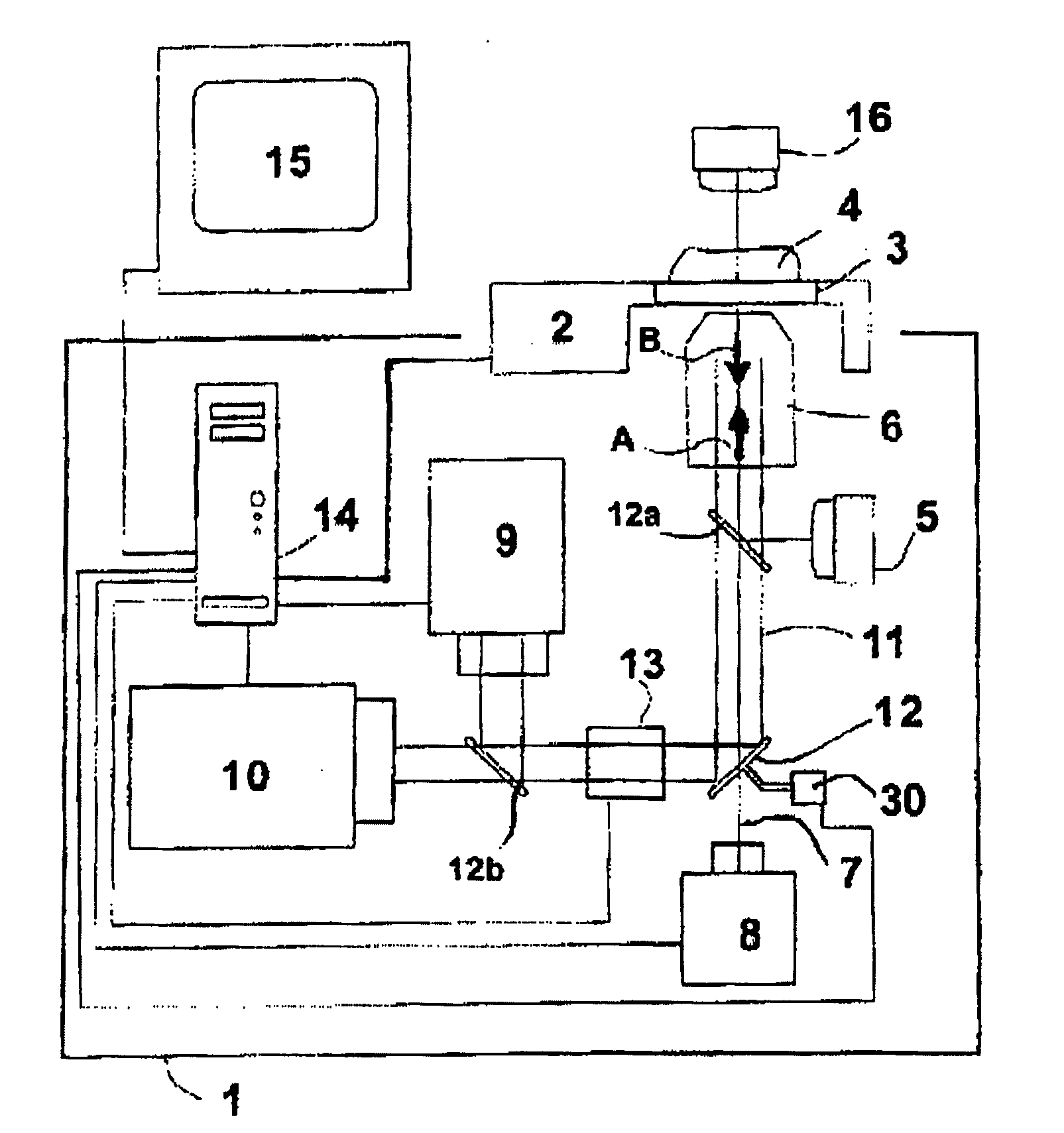
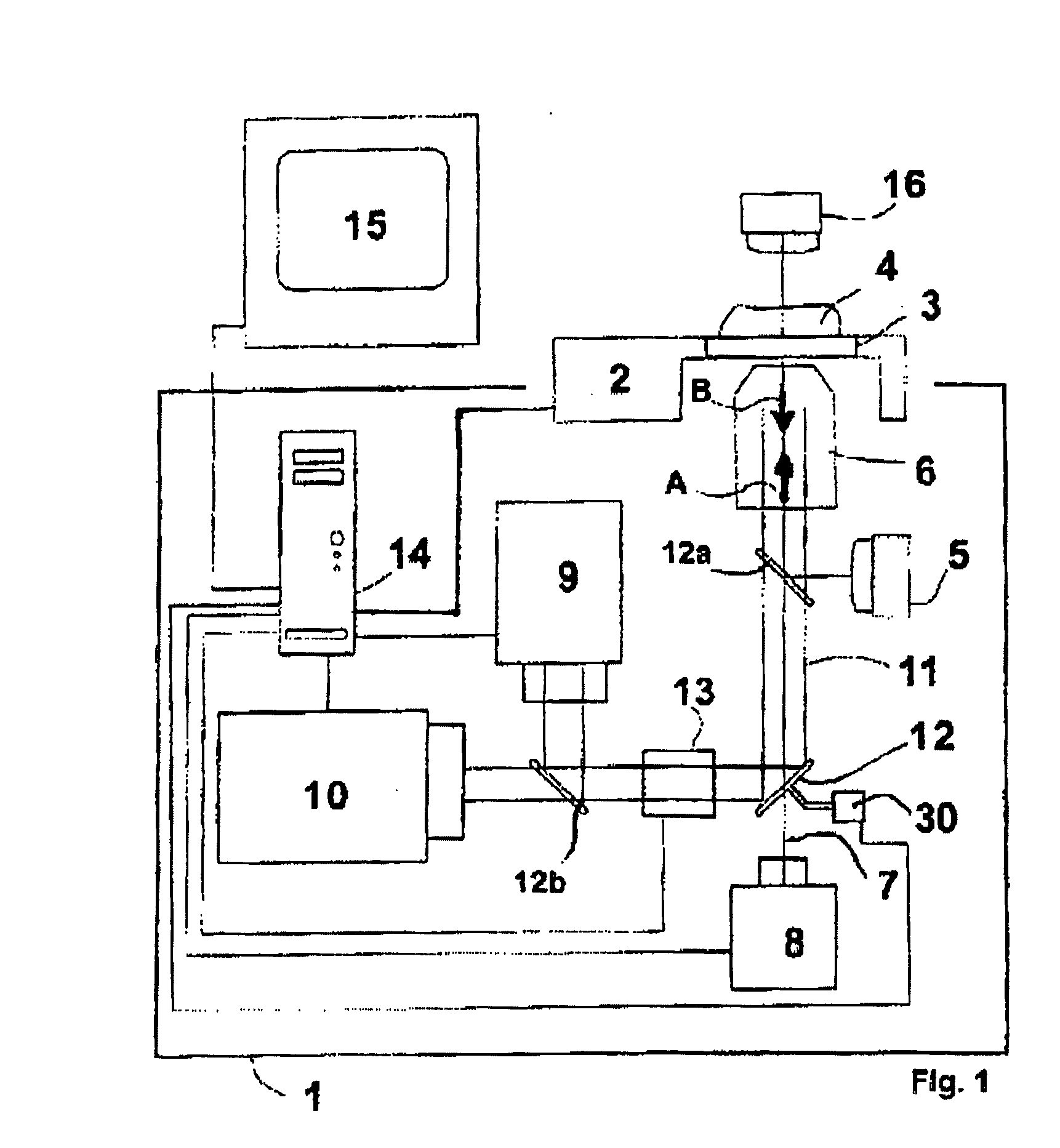
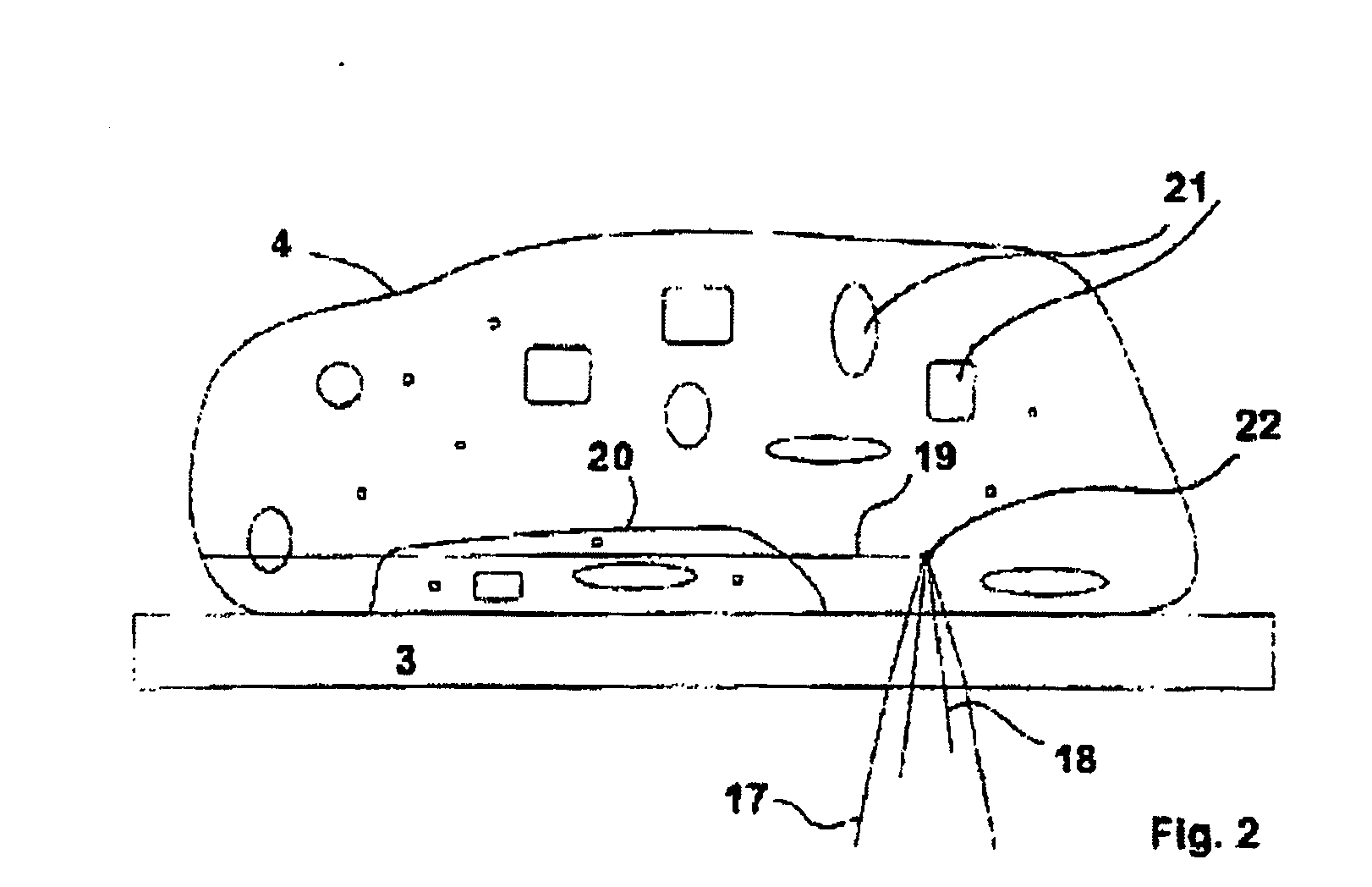
[0056] The microtome shown in FIG. 1 has a glass plate 3 as a support for the processed object (“sample”) 4. The glass plate 3 is connected to an XYZ traversing unit 2. By placing the sample 4 on the glass plate 3, for soft, flexible samples, advantageous smoothing is achieved. This smoothing action can optionally be intensified by a second glass plate (not shown) by the sample being inserted and pressed between this second glass plate and the glass plate 3.

[0057] On one side of the glass plate 3 there is a focussing objective lens 6 which has several lenses which are configured in the manner of a telescope (not shown). The distance of the lenses to one another and the distance of the lenses to the glass plate 3 can be varied. In this way the divergence / convergence of the laser beam 11 which runs through the focussing objective lens 6 is changed. The optical axis 7 of the focussing objective lens 6 is perpendicular to the plane of the glass plate 3.

[0058] Likewise, in the optical ...


PUM

PropertyMeasurementUnit
energyaaaaaaaaaa
pulse energyaaaaaaaaaa
frequencyaaaaaaaaaa

Abstract

The invention relates to a microtome, comprising a holding device with a support (3) for holding at least one portion of a processed object (4), and a severing means (6, 10, 13). Known microtomes of the aforementioned type have the disadvantage that the processed object must be fixed and there is limited freedom in the choice of guiding the cut. The invention avoids these disadvantages by the severing means comprising at least one laser radiation source (10) and means for focussing (6; 13) the laser radiation, and the beam focus (22) which has been produced by the focussing can be moved relative to the support (3) and can be guided to a location of the parting surface (19; 20) of the processed object (4) in order to effect severing of the material at this site. The invention furthermore relates to a process for microtomy which can be advantageously carried out with the microtome as claimed in the invention.

Description

FIELD OF THE INVENTION [0001] The invention relates to a microtome with a holding device with a support for holding at least one portion of a processed object, and a severing means. Another aspect of the invention relates to a process for microtomy of a processed object. BACKGROUND OF THE INVENTION [0002] Microtomes of the aforementioned type and the corresponding processes for microtomy are used to cut thin slices off a processed object which is to be studied in order to study it for example by means of a microscopic process. Microtomes are often used to obtain thin tissue sections from a tissue sample which can be studied by a transmitted light microscope. [0003] In the prior art microtomes are known which contain a clamping device for the processed object and a blade which can be moved relative to this clamping device. The blade is mounted to be able to move easily on a carriage and the cutting edge of the blade can be moved back and forth in a parting plane. The processed object...

Claims


Application Information

Patent Timeline
Patent Type & Authority Applications(United States)
IPC IPC(8): B26D1/00B23K26/38G01N1/06G01N1/28
CPCB23K26/381G01N1/06G01N1/2813G01N2001/284B23K26/4035B23K26/382B23K2103/32B23K2103/50Y10T83/929
Inventor KERMANI, OMID
Owner ROWIAK GMBH
Why Eureka
Try Eureka