Wireless power beaming to common electronic devices

a technology of electrical power beaming and electronic devices, applied in wave amplification devices, electrical equipment, laser details, etc., can solve the problems of insufficient outlets for all devices requiring power, affecting the service life of the device,

Inactive Publication Date: 2007-01-25
POWERBEAM
View PDF9 Cites 306 Cited by
  • Summary
  • Abstract
  • Description
  • Claims
  • Application Information

AI Technical Summary

Problems solved by technology

It can get tangled or be tripped on.
It may be unsightly.
There may be insufficient outlets for all of the devices requiring power.
This often involves a costly, difficult installation.
To move the speaker later becomes difficult.
There may be more cords and chargers than there are convenient outlets, and batteries may run out at inconvenient times during use.
This is usually limited to low-power devices.
These devices cannot be very powerful.
These cannot be very powerful at all.
As a result, solar cells are rarely used to power devices.
Currently no completely cordless solution for power to these kinds of common devices is available.
First, they are intentional emitters under Federal Communications Commission regulations.
Second, they can cause signal interference, and because they are regulated spectrum, any unwanted reflection will cause interference.
Third, the components to contain them are not as easy to manufacture and work with as optical components.
Fourth, they are unsafe around people.
They can burn a person.
They used non-eye-safe lasers in a manner that would not be safe or effective in a commercial application.
These methods had no way to account for where the optical energy went, or if it was within FDA permitted limits.
It does not provide sufficient power to drive a large load, like an audio speaker.
It does not have a system to assure that the human exposure remains within regulatory limits.
It does not show a means of delivering the optical power beam to the photovoltaic cell.
It is not suitable for use in a home or business because it lacks precautions to allow a human not wearing eye-safety goggles nearby, and because it has no means to avoid being blocked generally.
Line of sight is often not available in a home or business.
There is little prior art for use of a laser to power remote objects in the home or business because of safety issues, efficiency issues, and the difficulty of guaranteeing line-of-sight.

Method used


Image

  • Wireless power beaming to common electronic devices
  • Wireless power beaming to common electronic devices
  • Wireless power beaming to common electronic devices

Examples


embodiment 1a

[0073]FIG. 2 Embodiment 1A

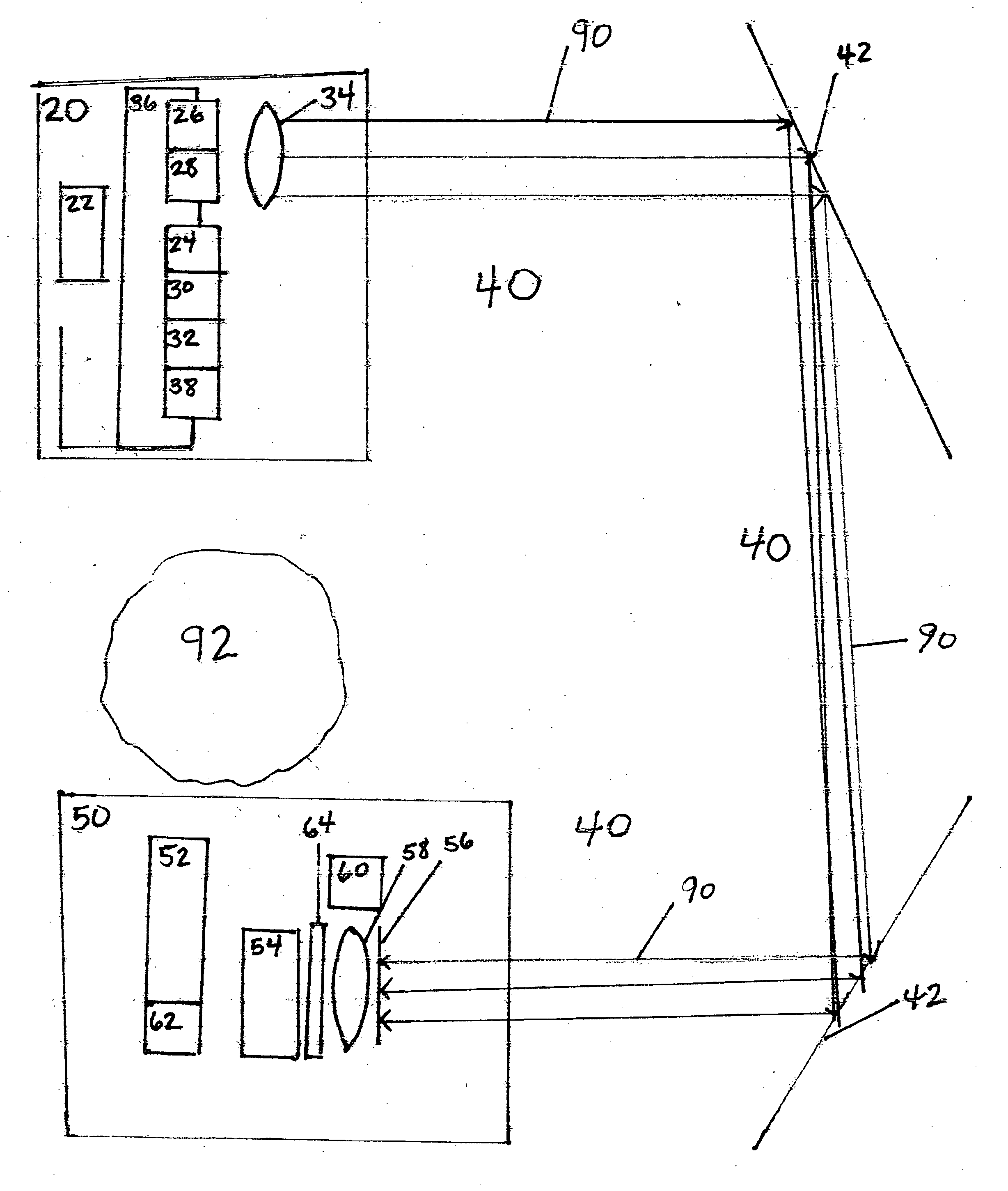
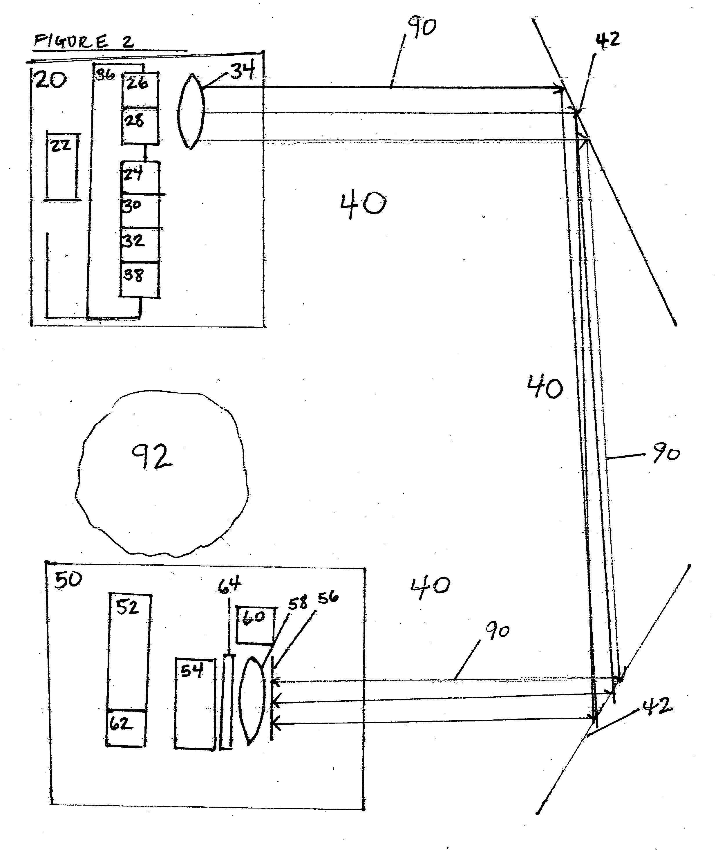
[0074] A preferred embodiment of the present invention is illustrated in FIG. 1A. This is for a system that might be used in a person's living room to illuminate a light attached to the ceiling. The load is assumed to require 20 Watts.

[0075] The preferred embodiment consists generally of transmitter assembly 20, free space 40, and optical to electrical converter 50.

[0076] Transmitter assembly 20 converts electricity to light. In the preferred embodiments, it uses an eye-safe diode laser(s) 26. These operate at >1500 nm wavelength. Such lasers are made by nLight Photonics, Inc, Princeton Lightwave, Covega, and other sources. Light 90 from the laser(s) 26 goes immediately into lens(es) 34 for focusing and pointing the lasers. In the preferred embodiment, the outgoing light 90 is nearly collimated, and the beam intensity is 1 mW / sq. mm-10 mW / sq.mm. The beam profile is substantially uniform.

[0077] The Transmitter assembly 20 must aim the light. To aim the li...

embodiment 1b

[0084]FIG. 3 Embodiment 1B

[0085] A preferred embodiment of the present invention is illustrated in FIG. 1B. This is for a system that might be used in a café or office to charge cell phones, laptops, etc. The load of a cell phone is 3-5 W and of a laptop 30-50 W. The elements are the same.

[0086] The elements of Embodiment 1B are the same as those for Embodiment 1A except as described here.

[0087] Transmit assembly 20 is assumed to be on the ceiling pointing downward for this embodiment. Obstruction 92 does not exist, so mirror 42 is not used. In embodiment 1B, the loads, the cell phones, place different requirements on the system.

[0088] Cell phones move, and may be anywhere. Pointing mechanism 36 is powered and controlled from the CPU 22. It may be a powered pan-and tilt system, as is commonly seen on security cameras. In an alternate embodiment, pointing mechanism 36 may be fixed, and an actuated mirror may be used to alter the beampath and allow the camera to scan.

[0089] Becaus...


PUM


Abstract

A method and apparatus for wireless power beaming consisting of a transmitter assembly (20), free space (40), and an optical-to-electric assembly (50). The transmitter assembly (20) has eye-safe lasers (26) that create a beam of light (90). The beam of light goes through free space (40) and impinges upon the surface of optical-to-electric assembly (50). Optical-to-electric assembly (50) has power conversion photodiode(s) (54) to convert the energy in the light (90) into electricity. Power Accounting (14) accounts for the power in the beam and controls the lasers to turn them off whenever radiation is not accounted for in the system.

Description

CROSS-REFERENCE TO RELATED APPLICATION(S) [0001] This application claims the benefit of provisional patent application Ser. No. 40 / 659,357. filed 2005 Mar. 9 by the present inventor.FEDERALLY SPONSORED RESEARCH [0002] Not applicable. SEQUENCE LISTING OR PROGRAM [0003] Not applicable. BACKGROUND OF THE INVENTION [0004] 1. Field of the Invention [0005] This invention relates to providing electrical power to electronic devices without a wire or other connection to a power source. It also relates to providing electronic signals to the device without a wire connection. [0006] 2. Prior Art [0007] The current state-of-the-art in common home and business electrical and electronic devices is that they receive power from five types of sources. [0008] 1. Many are plugged into a wall outlet. An example would be a lamp with a power cord. In this case, the cord usually requires proximity to a wall outlet. It can get tangled or be tripped on. It may be unsightly. There may be insufficient outlets ...

Claims


Application Information

Patent Timeline
Patent Type & Authority Applications(United States)
IPC IPC(8): H01S3/00
CPCH02J17/00H02J50/30
Inventor GRAHAM, DAVID SILLIMAN
Owner POWERBEAM
Why Eureka
Try Eureka