PDC drill bit using optimized side rake angle

a fixed cutter and drill bit technology, applied in the direction of manufacturing tools, metal-working drilling tools, and wellbore/well accessories, can solve the problems of significant expense involved in the design and manufacture of drill bits and in the drilling of wells, and achieve the effect of optimizing the performance of fixed cutter drill bits

Active Publication Date: 2006-08-17
SMITH INT INC
View PDF43 Cites 80 Cited by
  • Summary
  • Abstract
  • Description
  • Claims
  • Application Information

AI Technical Summary

Benefits of technology

[0012] The invention relates to methods for modeling the performance of fixed cutter bit drilling earth formations. The invention also relates to methods for designing fixed cutter drill bits and methods for optimizing drilling parameters for the drilling performance of a fixed cutter bit. In one embodiment, the invention relates to modifying a side rake angle distribution for cutters on the drill bit to improve and / or to optimize performance of a fixed cutter drill bit that is modeled.

Problems solved by technology

Significant expense is involved in the design and manufacture of drill bits and in the drilling of well bores.

Method used


Image

  • PDC drill bit using optimized side rake angle
  • PDC drill bit using optimized side rake angle
  • PDC drill bit using optimized side rake angle

Examples


example alternative embodiments

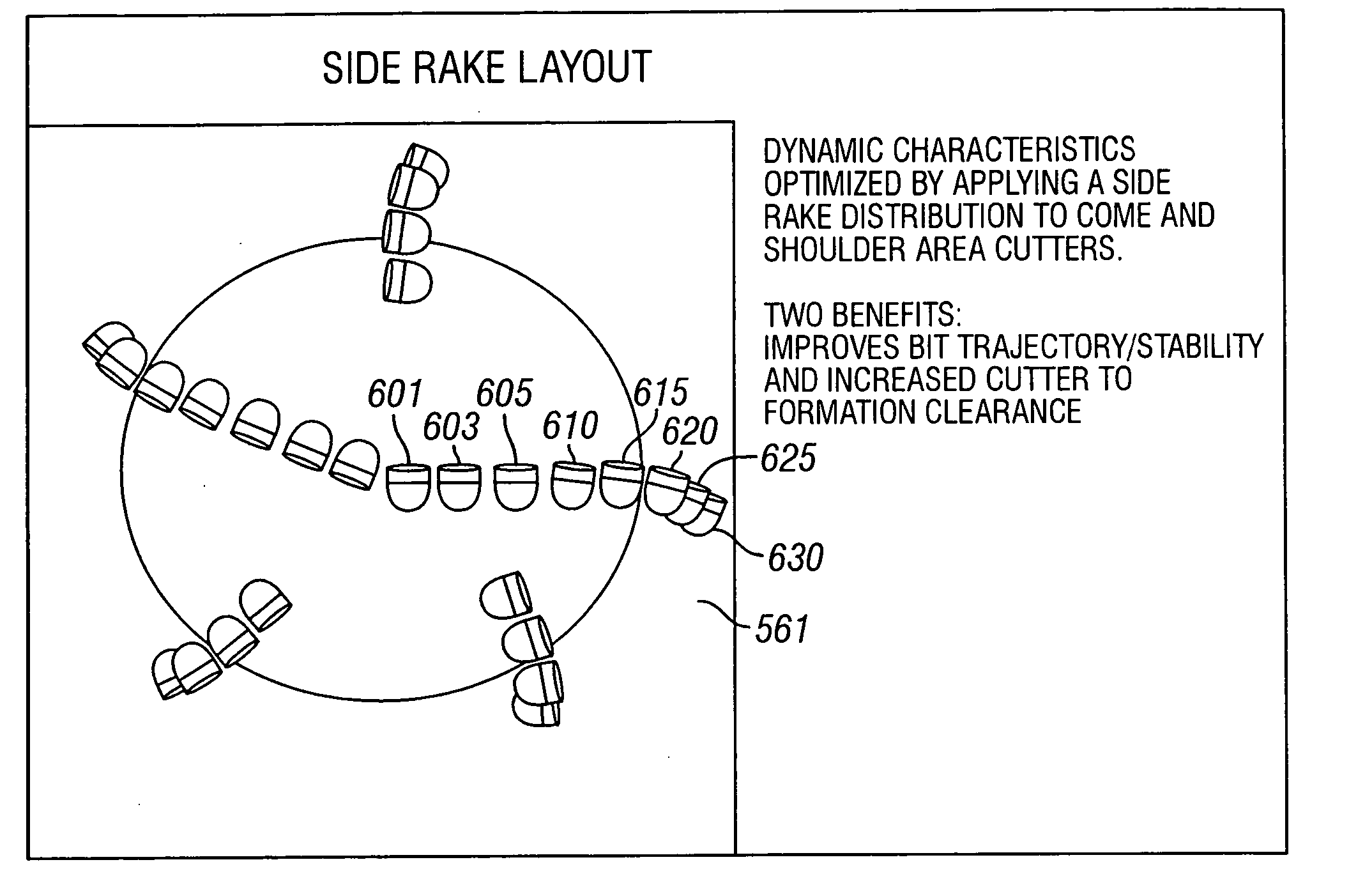
[0198]FIG. 30 shows a partial end view of a fixed cutter bit 1200 with an alternative modification of the distribution of side rake angles along one exemplary blade 1202 having cutters 1204, 1206, 1208, 1210, and 1212 in a cone region 1214 that are positioned with their faces 1216 parallel to a radial plane 1220 through the centerline 1222 of the bit 1200. By moving the cutters 1204, 1206, 1208, 1210, and 1212 forward of the radial plane 1220 without tilting the cutters, the faces 1216 continue to be parallel to the radial plane 1220. However the offset distance 1218 causes the tangent lines 1224, 1226, 1228, 1230 and 1232 at the face of each cutter 1204, 1206, 1208, 1210, and 1212 to be at a different side rake angle 1234, 1236, 1238, 1240 and 1242, respectively, relative to the centerlines of each cutter. Thus, the side rake angle for each cutter is different and relatively larger at the center cutter 1204 and relatively smaller at cutter 1212. This shows an alternative way to mod...


PUM


Abstract

A fixed cutter drill bit and a method for designing a fixed cutter drill bit includes simulating the fixed cutter drill bit drilling in an earth formation. A performance characteristic of the simulated fixed cutter drill bit is determined. A side rake angle distribution of the cutters is adjusted at least along a cone region of a blade of the fixed cutter drill bit to change the performance characteristic of the fixed cutter drill bit.

Description

CROSS-REFERENCE TO RELATED APPLICATIONS [0001] This is an application for patent and is a continuation-in-part of co-pending and co-owned U.S. patent application Ser. No. 11 / 041,895 entitled “PDC Drill Bit Using Optimised Side Rake Distribution that Minimized Vibration and Deviation” filed on Jan. 24, 2005, which is related to co-pending and co-owned U.S. patent application Ser. No. 10 / 888,523 entitled “Methods For Designing Fixed Cutter Bits and Bits Made Using Such Methods” filed on Jul. 9, 2004, U.S. patent application Ser. No. 10 / 888,358 entitled “Methods For Modeling, Displaying, Designing, And Optimizing Fixed Cutter Bits filed on Jul. 9, 2004, U.S. patent application Ser. No. 10 / 888,354 entitled “Methods for Modeling Wear of Fixed Cutter Bits and for Designing and Optimizing Fixed Cutter Bits,” filed on Jul. 9, 2004, and U.S. patent application Ser. No. 10 / 888,446 entitled “Methods For Modeling, Designing, and Optimizing Drilling Tool Assemblies,” filed on Jul. 9, 2004, all o...

Claims


Application Information

Patent Timeline
Patent Type & Authority Applications(United States)
IPC IPC(8): E21B10/36
CPCE21B10/42G06F17/5009G06F30/20E21B41/0092E21B10/46E21B10/62
Inventor DURAIRAJAN, BALACARIVEAU, PETER THOMASHUANG, SUJIAN J.
Owner SMITH INT INC
Why Eureka
Try Eureka