
Fuel cell system and control method for the same

Pending Publication Date: 2022-10-13
DOOSAN MOBILITY INNOVATION INC
View PDF0 Cites 0 Cited by
  • Summary
  • Abstract
  • Description
  • Claims
  • Application Information

AI Technical Summary

Benefits of technology

The present invention provides a fuel cell system and control method that can improve its operation performance by supplying moisture from one or more stacks of a plurality of stacks to one or more other stacks according to their humidity requirements. The duct may be configured to seal the stacks so that air does not leak outside. The multiple stacks are operated in forward / reverse directions to maintain their moisture balance and optimize their performance. By switching the flow of hydrogen fuel or air fuel in the forward / reverse direction, impurities can be prevented from being deposited and ventilation can be minimized, leading to higher fuel utilization.

Problems solved by technology

Since the water cooling type uses high-mass cooling water, it has better cooling capacity compared to the air-cooling type using low-mass air, but it requires a separate device, so it may be suitable for electric vehicles, etc. but is not suitable for flying objects such as drones that are sensitive to weight.
However, in the case of an air-cooled fuel cell system, it is difficult to specify the operation environment of the stack due to its simple structure, and in particular, there is a limitation in being vulnerable to humidification, which is a key element of the stack.
If the stack is not humidified properly and the humidity inside the stack is lowered, it may cause a problem of degradation of the stack performance.
However, there is a problem in that the performance of the stack is degraded due to the accumulation of impurities such as water vapor or nitrogen.
As a result, the hydrogen fuel has no choice but to be discharged (ventilated) to the outside, which lowers the fuel utilization rate.

Method used


Image

  • Fuel cell system and control method for the same
  • Fuel cell system and control method for the same
  • Fuel cell system and control method for the same

Examples


first embodiment

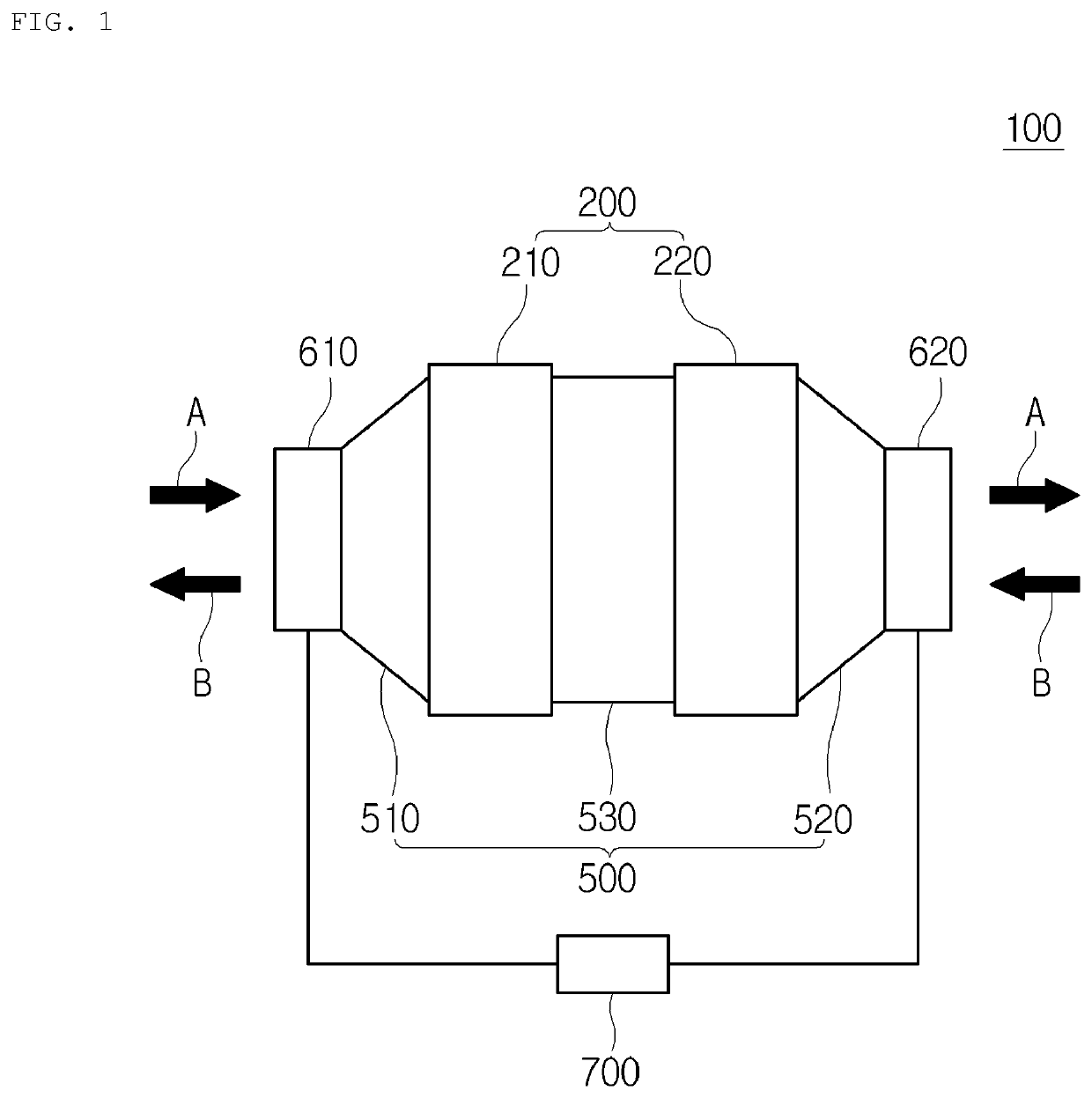
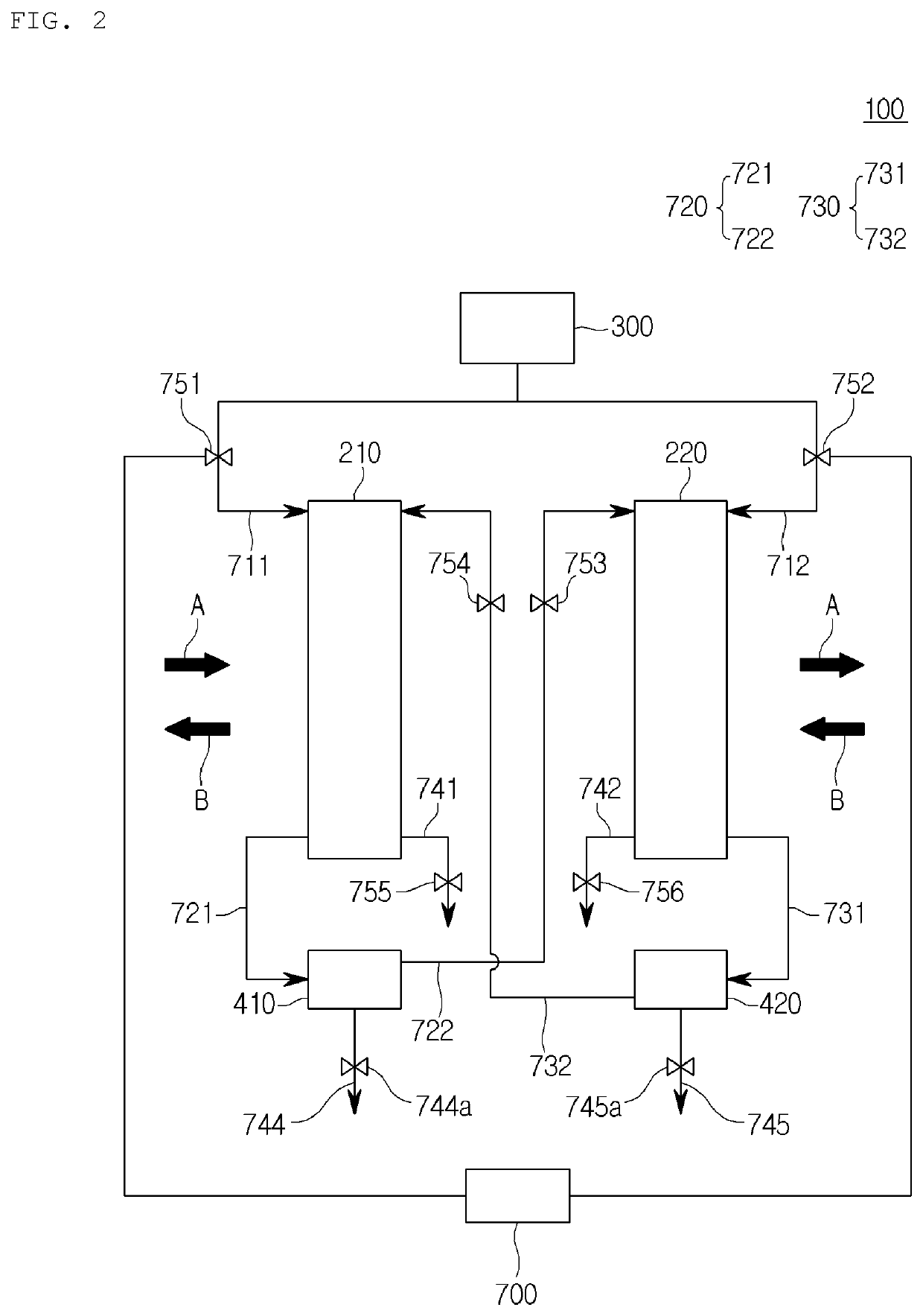
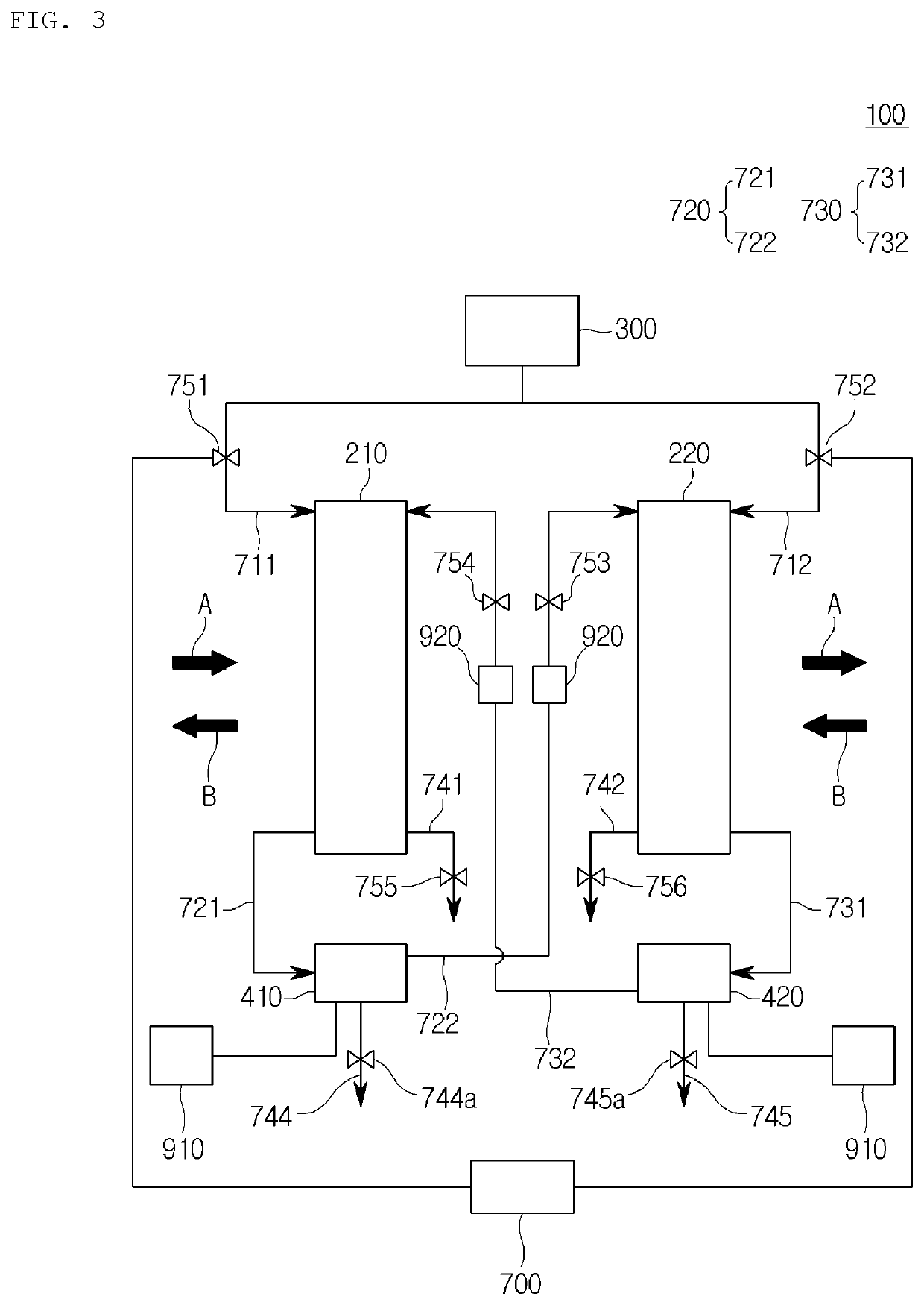
[0052]Referring to FIGS. 1 and 2, the fuel cell system 100 according to the present invention may be configured to include first and second stacks 210, 220, a fuel tank 300, first and second water traps 410, 420, and a duct 500, a blower 600 and a control unit 700.

[0053]A first-1 connection fuel pipe 721 and a first-2 connection fuel pipe 722 described below may be a sub-concept of a first connection fuel pipe 720. That is, the first connection fuel pipe 720 may include the first-1 connection fuel pipe 721 connecting the first stack 210 and the first water trap 410, and the first-2 connection fuel pipe 722 connecting the first water trap 410 and the second stack 220. The unreacted hydrogen fuel that has passed through the first stack 210 and the water in a liquid or gaseous state generated in the first stack 210 may flow in the first connection fuel pipe 720.

[0054]In addition, a second-1 connection fuel pipe 731 and a second-2 connection fuel pipe 732 may be a sub-concept of a secon...

second embodiment

[0159]With reference to FIGS. 4 and 5, the fuel cell system 100 according to the present invention may be configured to include the first, second, and third stacks 210, 220, 230, the fuel tank 300, and the first, second, and third water traps 410, 420, 430, the duct 500 and the blower 600.

[0160]The first-1 connection fuel pipe 721, the first-2 connection fuel pipe 722, the first-3 connection fuel pipe 723 and the first-4 connection fuel pipe 724 described below may be a sub-concept of the connection fuel pipe 720, and the second-1 connection fuel pipe 731, the second-2 connection fuel pipe 732, the second-3 connection fuel pipe 733 and the second-4 connection fuel pipe 733 may be a sub-concept of the second connection fuel pipe 730, and the unreacted hydrogen fuel in each stack and the water generated in each stack may flow in the first and second connection fuel pipes 720, 730.

[0161]The first stack 210 may be a stack for a fuel cell in which a plurality of cells each having an anod...


PUM


Abstract

The present invention relates to a fuel cell system and a control method for the same, it may be configured to include a plurality of stacks connected in series with each other, and supply moisture from one or more stacks of the plurality of stacks to one or more other stacks according to an operation condition of each of the plurality of stacks, and it has an advantage of improving an operation performance by uniformly forming the humidity condition of each of the plurality of stacks.

Description

CROSS REFERENCE TO RELATED APPLICATION[0001]The present application claims priority to Korean Patent Application No. 10-2021-0046628, filed Apr. 9, 2021, the entire contents of which is incorporated herein for all purposes by this reference.BACKGROUND OF THE INVENTIONField of the Invention[0002]The present invention relates to a fuel cell system and control method for the same, and more particularly, to a fuel cell system and control method for the same which can improve operation performance by supplying moisture from one or more stacks of a plurality of stacks to one or more other stacks according to an operation condition of each of the plurality of stacks to uniformly form a humidity condition for each of the plurality of stacks.Description of the Related Art[0003]As a high-efficiency clean energy source, a fuel cell is gradually expanding its use area. Among various types of fuel cells, in particular, a polymer electrolyte membrane fuel cell (PEMFC) is superior to other types o...

Claims


Application Information

Patent Timeline
IPC IPC(8): H01M8/04828H01M8/24
CPCH01M8/04835H01M8/24H01M8/249H01M8/04126H01M8/04298H01M8/04828H01M8/2465H01M8/2484Y02E60/50H01M8/04089H01M8/04164H01M8/04492H01M8/04753H01M8/04156H01M8/04679
Inventor LEE, HYEONG GEUNWON, HO KEUNBUM, KIL HOLEE, CHANG SEONSEO, JI SUNG
Owner DOOSAN MOBILITY INNOVATION INC
Learn More