

Organic electronic device
a technology of electronic devices and thin films, applied in the direction of organic chemistry, group 5/15 element organic compounds, luminescent compositions, etc., can solve the problems of difficult processing, high reactiveness, and high voltage requirements of thin film transistors (otfts)
- Summary
- Abstract
- Description
- Claims
- Application Information
AI Technical Summary
Benefits of technology
Problems solved by technology
Method used
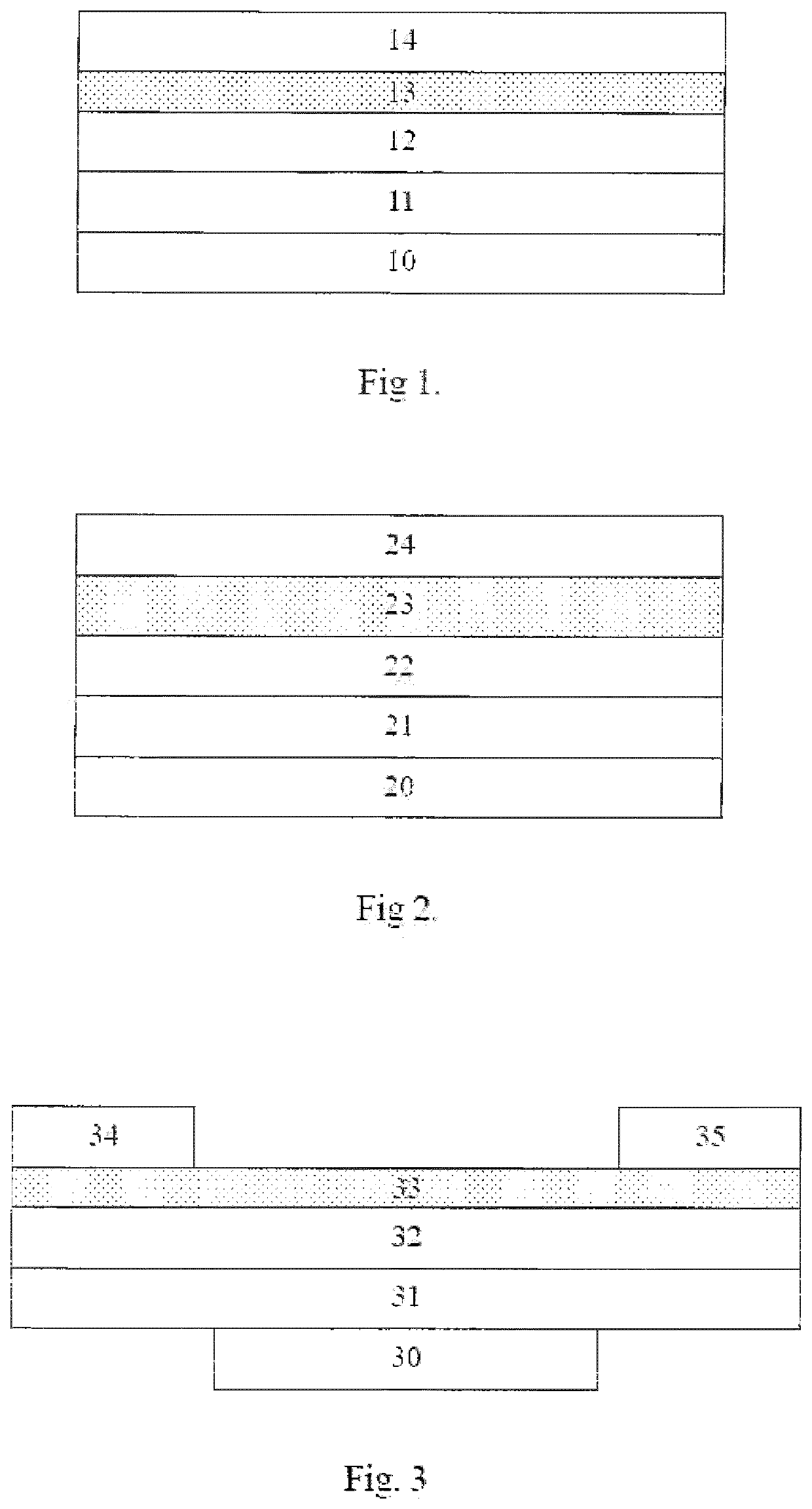
Image

Examples
example 2
-(diphenylphosphoryl)quinolin-8-olate (2)
[0106]
Step 1: synthesis of quinolin-8-yl diphenylphosphinate
[0107]10 g 8-hydroxyquinoline were dissolved in 170 mL dry THF. 17.9 g (1.1 eq.) diphenylphosphoryl chloride and 7.7 g (1.1 eq.) diisopropylamine were added at room temperature. After stirring overnight, the reaction mixture was filtered, then evaporated to dryness and treated with 40 mL hexane. 23.5 g white solid were obtained (98% yield), GCMS gives 100% purity.
Step 2: synthesis of lithium 7-(diphenylphosphoryl)quinolin-8-olate (2)
[0108]7 g quinolin-8-yl diphenylphosphinate from the previous step were dissolved in 120 mL dry THF under argon. The clear solution was cooled to −80° C. 14.9 mL (1.1 eq.) of 1.5 M lithium diisopropylamide solution in cyclohexane were added dropwise as to the starting compound. The reaction mixture was allowed to return to room temperature overnight and further stirred for one entire week. Then, an addition of 100 mL n-hexane afforded a precipitate that w...
example 3
-(diphenylphosphoryl)quinolin-3-olate (3)
[0109]
Step 1: synthesis of diphenyl(quinolin-2-yl)phosphine oxide
[0110]4 g 2-chloroquinoline (1 eq.) were dissolved in 50 mL dry THF under argon. To this solution, 48.9 mL (1 eq.) of commercial 0.5 M solution of potassium diphenylphosphite in THF were added at room temperature over 90 minutes. After stirring overnight at room temperature, the solution was evaporated to dryness and the residue suspended in 80 mL dichloromethane and treated with 20 mL of 30 wt. % hydrogen peroxide aqueous solution. After 3 h stirring at room temperature, the organic phase was washed twice with 30 mL brine and twice with 30 mL distilled water, dried over magnesium sulfate, filtered and evaporated. The residue was precipitated from dichloromethane / hexane to obtain 4.62 g (57% yield) of a pale yellow solid. HPLC showed 99.2% purity.
Step 2: synthesis of (3-hydroxyquinolin-2-yl)diphenylphosphine oxide
[0111]4.5 g (1 eq.) diphenyl(quinolin-2-yl)phosphine oxide were di...
example 4
-(diphenylphosphoryl)pyridin-2-olate (4)
[0113]
Step 1: synthesis of diphenyl(pyridin-3-yl)phosphine oxide
[0114]110 mL of a 0.5 M potassium diphenylphosphite solution in THF were diluted with 110 mL dry THF under argon. 8 g 3-fluoropyridine were added dropwise at 0° C. to this solution during 30 minutes. The mixture was stirred overnight at room temperature, then evaporated to dryness and redissolved in 150 mL dichloromethane. The mixture was treated with 17 mL 30% aqueous hydrogen peroxide overnight. The organic phase was then washed twice with 30 mL brine and three times with 40 mL distilled water, then dried over magnesium sulfate, filtered and evaporated. The resulting oil was precipitated by addition 30 mL hexane and an ultrasound treatment. Isolated 12.1 g of a white solid (79% yield), GCMS showed 100% purity.
Step 2: synthesis of (2-hydroxypyridin-3-yl)diphenylphosphine oxide
[0115]5 g diphenyl(pyridin-3-yl)phosphine oxide were dissolved in 100 mL dry THF under argon and the solu...
PUM
| Property | Measurement | Unit |
|---|---|---|
| weight % | aaaaa | aaaaa |
| wt. % | aaaaa | aaaaa |
| thickness | aaaaa | aaaaa |
Abstract
Description
Claims
Application Information