Sheet guide apparatus
- Summary
- Abstract
- Description
- Claims
- Application Information
AI Technical Summary
Benefits of technology
Problems solved by technology
Method used
Image

Examples
first embodiment
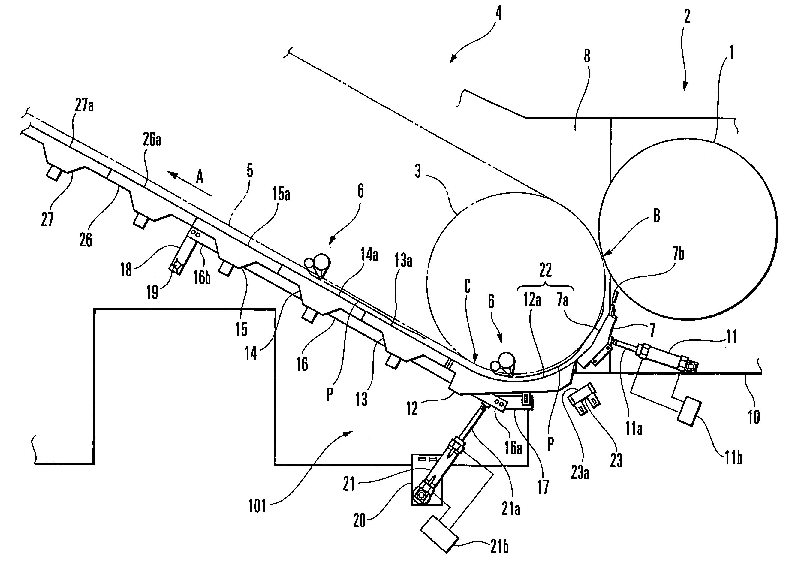
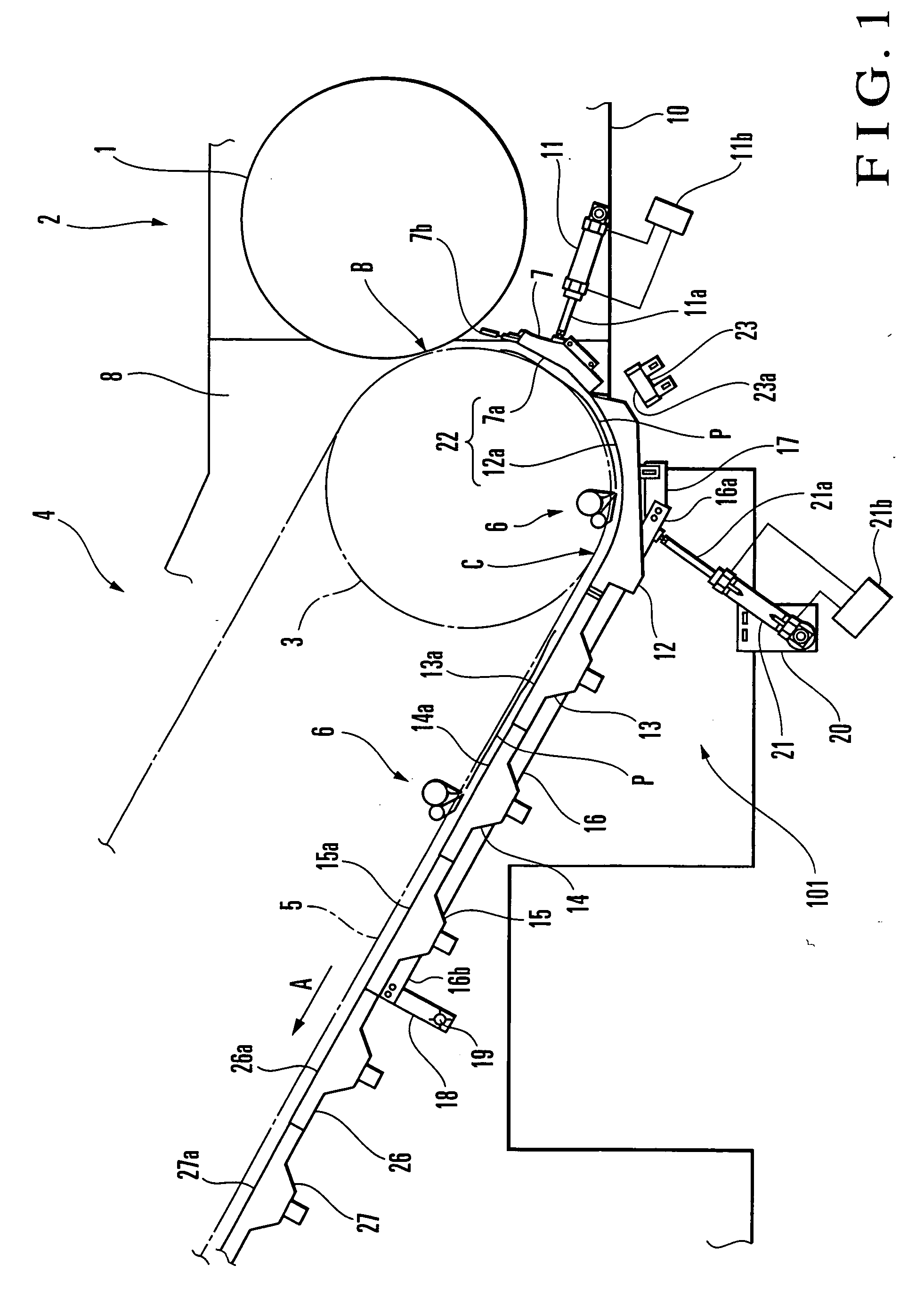
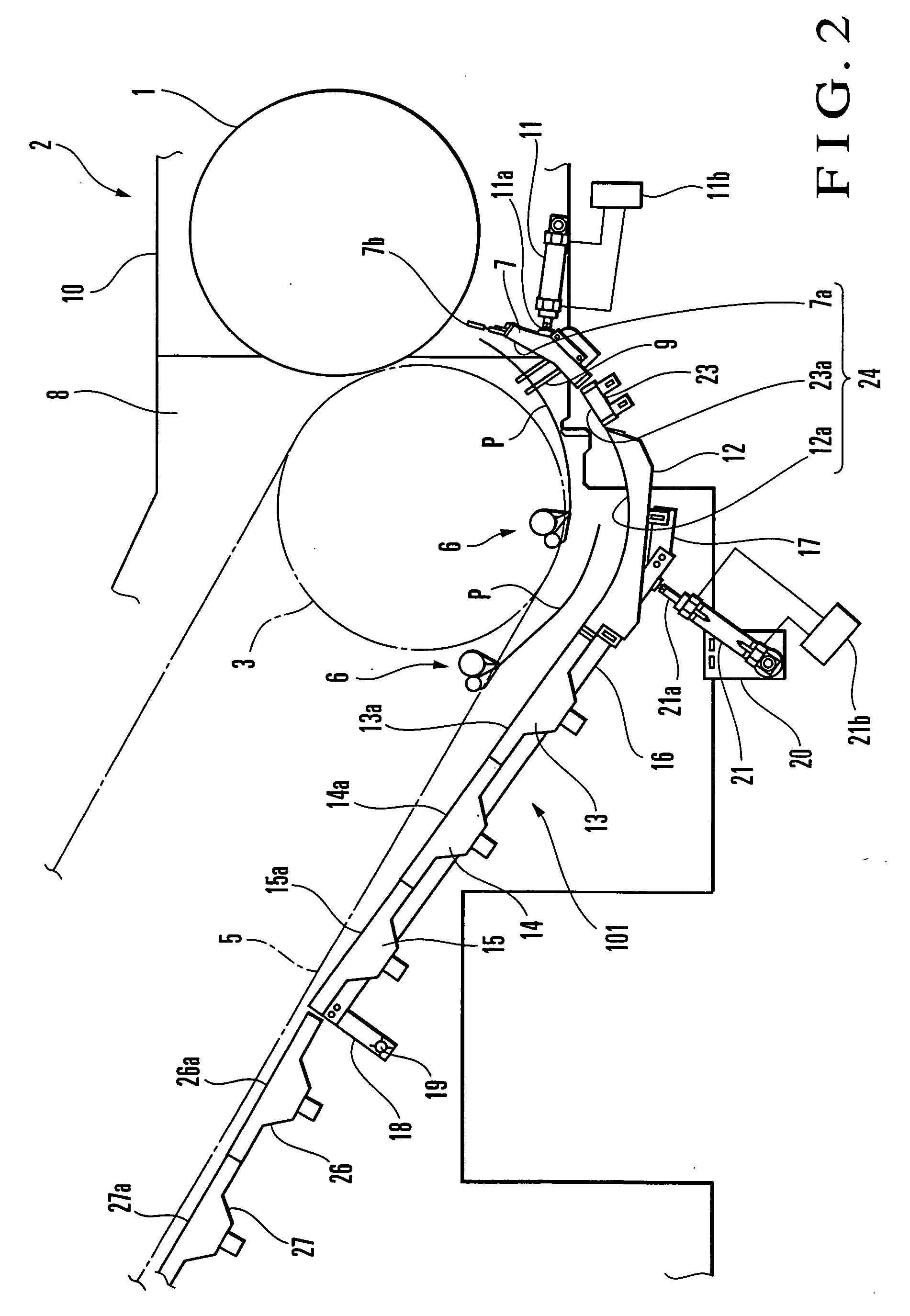
[0013] A sheet guide apparatus according to the present invention will be described with reference to FIGS. 1 to 3. A printing unit 2 of a sheet-fed perfecter comprises a plurality of printing units (not shown) corresponding to different colors. A transfer cylinder 1 serving as a transport cylinder is arranged at the final end of a cylinder group that forms the final printing unit. A delivery cylinder 3 which forms an arcuate convey path is arranged to oppose the transfer cylinder 1. A pair of delivery chains 5 (one delivery chain is not shown) serving as a convey means are looped around a sprocket (not shown) coaxial with the delivery cylinder 3 and a sprocket (not shown) at the rear end of a delivery unit 4 of the sheet-fed perfecter.
[0014] A plurality of gripper bars (not shown) are supported between the pair of delivery chains 5 at a constant interval in a traveling direction A of the delivery chains 5. A plurality of delivery grippers 6 each comprising a gripper and gripper pad...
second embodiment
[0039] the present invention will be described with reference to FIGS. 4A and 4B. In FIG. 4A, an inverted-J-shaped movable guide member 50 integrally comprises a curved portion 51 and linear portion 52. The curved portion 51 has a guide surface 51a with an arcuate section having substantially the same curvature as that of the outer surface of an opposing delivery cylinder 3. The linear portion 52 is continuous to the curved portion 51 and has a linear guide surface 52a. The movable guide member 50 is swingably supported by a pivot shaft 53 which is connected to the downstream end of the linear portion 52 in the sheet convey direction and supported by delivery frames. An air cylinder 55 having a rod 55a is pivotally mounted on the delivery frames, and the rod 55a is connected to the center of the curved portion 51 of the movable guide member 50. Supply and discharge of pressurized air of the air cylinder 55 are controlled by a solenoid valve unit 55b.
[0040] When the rod 55a of the a...
third embodiment
[0049] the present invention will be described with reference to FIGS. 5A and 5B. In FIG. 5A, a transfer cylinder 60 is arranged between two impression cylinders 61 and 62 to serve as a convey means which opposes each of the impression cylinders 61 and 62. First and second movable guide members 63 and 64 respectively having first and second guide surfaces 63a and 64a each with the same curvature as that of the outer surface of the transfer cylinder 60 are arranged to oppose the outer surface of the transfer cylinder 60. The cylinder ends of air cylinders 65 and 66 respectively having rods 65a and 66a are pivotally mounted on printing press frames, and the distal ends of the rods 65a and 66a of the air cylinders 65 and 66 are respectively pivotally mounted on the first and second movable guide members 63 and 64. Supply and discharge of pressurized air of the air cylinders 65 and 66 are controlled by solenoid valve units 65b and 66b.
[0050] When the rods 65a and 66a of the air cylinde...
PUM
 Abstract
Description
Claims
Application Information
 - R&D Engineer
- R&D Manager
- IP Professional
- Industry Leading Data Capabilities
- Powerful AI technology
- Patent DNA Extraction
Browse by: Latest US Patents, China's latest patents, Technical Efficacy Thesaurus, Application Domain, Technology Topic.
© 2024 PatSnap. All rights reserved.Legal|Privacy policy|Modern Slavery Act Transparency Statement|Sitemap