Encoder-equipped sealing device

a sealing device and encoder technology, applied in the field of encoder-equipped sealing devices or sealing devices, can solve the problems of difficult removal of units, affecting the working efficiency of the fitting device, and the fitting device to become non-operational, so as to achieve the highest reliability, easy to remove, and achieve the effect of more reliably

Inactive Publication Date: 2006-08-17
TOMIOKA MASANORI
View PDF11 Cites 2 Cited by
  • Summary
  • Abstract
  • Description
  • Claims
  • Application Information

AI Technical Summary

Benefits of technology

[0051] That is to say, even if the plural units of the encoder-equipped sealing device are placed one over the other so that they are oriented in one particular direction, the encoder-equipped sealing device can be slid relative to the other without causing any problems. Also, either of the two units that are located adjacently can be moved away from the other without causing any problems, so that individual units of the encoder-equipped sealing device can be handled easily after detaching them from each other. Thus, the encoder-equipped sealing device of the present invention can be slid smoothly out of the magazine equipped in the fitting tool, without causing any problems such as being caught or stuck. Thus, the encoder-equipped sealing device can be mounted on the area that ...

Problems solved by technology

When such cohesion occurs, the two units may attract each other magnetically within the magazine, from which it is difficult to remove the units by using any appropriate fitting device for mounting the units on the area that needs to be sealed, such as the appropriate area in the bearing unit....

Method used


Image

  • Encoder-equipped sealing device
  • Encoder-equipped sealing device
  • Encoder-equipped sealing device

Examples


Embodiment Construction

[0058] Several preferred embodiments of the present invention are now described below by referring to the accompanying drawings.

[0059] It should be noted that the encoder-equipped sealing device according to the prior art that has been described so far by referring to FIG. 5 and the encoder-equipped sealing device according to the various embodiments of the present invention that will be described below by referring to FIGS. 1 through 4 contain some common parts, elements or members. In the following description, those common parts, elements or members are given the same reference numerals, and are not described to avoid the duplication.

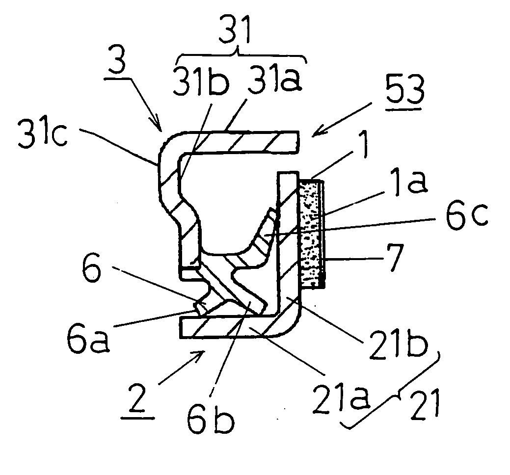
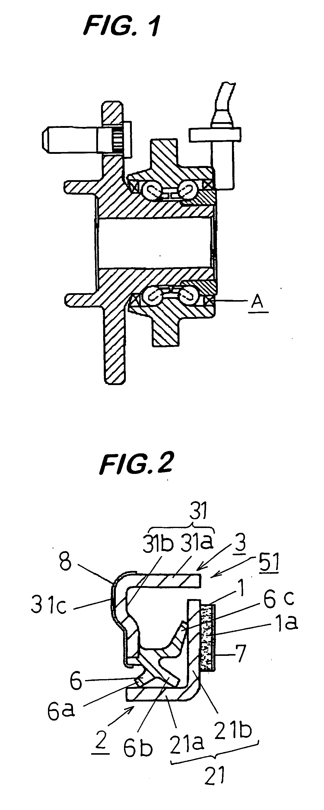
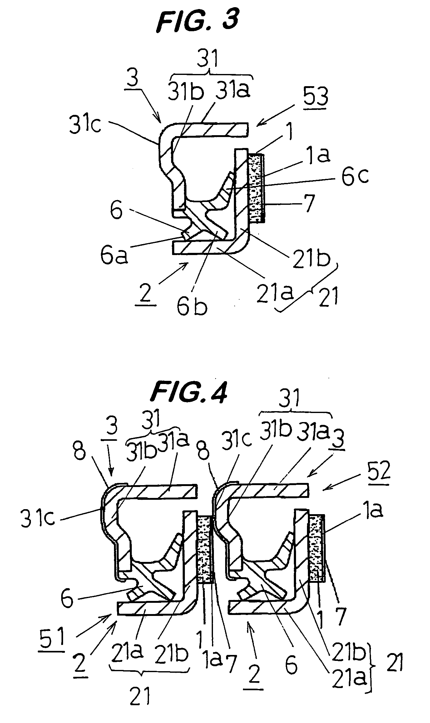
[0060] Referring first to FIG. 2, a first unit of the encoder-equipped sealing device according to one embodiment of the present invention, which is identified by reference number 51, is described, wherein a coating layer 8 is formed on the side 31c (located on the left side in FIG. 2) of a first seal element 3 opposite the side on which the seal e...


PUM


Abstract

A sealing device has an encoder incorporated therein, and includes a combination of seal elements (3, 2), each of which includes an annular metal core (31, 21) having a substantially L-shaped cross section having a cylindrical portion (31a, 21a) and a flange portion (31b, 21b) provided on one end of the cylindrical portion (31a, 21a) and extending in the direction perpendicular to the direction in which the cylindrical portion (31a, 21a) extends. A first seal element (3) of the two seal elements (3, 2) and the second seal element (2) are combined together such that the space defined by the cylindrical portion (31a) and flange portion (31b) of the first seal element (3) and the space defined by the cylindrical portion (21a) and flange portion (31b) of the second seal element (2) face each other. The first seal element (3) further includes an elastic seal portion (6) provided on the flange portion (31b) and disposed in the space defined by the cylindrical portion (31a) and flange portion (31b), and the second seal element (2) further includes a magnet-based encoder (1) provided on the flange portion (21b). A coating layer (8, 7) is provided on the side (31c) of the first seal element (3) opposite the side on which the first seal element (3) is combined with (faces) the second seal element (2), or on the side (1a) of the second seal element (2) opposite the side on which the second seal element (2) is combined with (faces) the first seal element (3), or on both of the sides (31c) and (1a).

Description

[0001] This application is a continuation of U.S. application Ser. No. 10 / 776,261, filed Feb. 12, 2004, now pending.BACKGROUND [0002] 1. Field of the Invention [0003] The present invention relates to an improvement to and / or in the encoder-equipped sealing device or sealing device that has a magnet-based encoder incorporated therein. More particularly, the present invention relates to such encoder-equipped sealing device that provides the capabilities for preventing the physical cohesion by the magnetic attraction from occurring between two or more units of the encoder-based sealing device that are adjacent to each other, when those units are placed one over another so that those units are oriented in one particular direction. [0004] 2. Description of the Prior Art [0005] The encoder (pulse coder) that is incorporated in the encoder-equipped sealing device that has been described above takes the form of a pulse generator ring that may be mounted on an automotive vehicle in order to ...

Claims


Application Information

Patent Timeline
IPC IPC(8): F16J15/32G01D5/12F16C33/78F16C41/00G01P3/44G01P3/487
CPCF16C33/7879F16C41/007F16J15/326G01P3/443G01P3/487F16C2326/02F16C19/186
Inventor TOMIOKA, MASANORI
Owner TOMIOKA MASANORI
Why Eureka
Try Eureka