Rotor device capable of forcing heat dissipation

Active Publication Date: 2006-08-17
ASIA VITAL COMPONENTS SHENZHEN CO LTD
View PDF6 Cites 19 Cited by
  • Summary
  • Abstract
  • Description
  • Claims
  • Application Information

AI Technical Summary

Benefits of technology

[0008] An object of the present invention is to provide a rotor device capable of forcing heat dissipation in which the hub provides a closed end with at least a through hole and a projection and the projection extends from the closed end along circumference of the through hole so that the projection forces the fluid to move inward or outward via the through hole to reduce temperature of the fluid in the hub.
[0009] In order to achieve the preceding object,

Problems solved by technology

However, the problem of conventional rotor assembly resides in that heat can be generated from running of the stator 13 and the rotor 15 and most of the heat stays in the hub without removing because of the shield member being enclosed in the hub with poor heat transfer.
In this way, a great deal of heat stays in the hub to lead shortened life span of the motor and to increase

Method used


Image

  • Rotor device capable of forcing heat dissipation
  • Rotor device capable of forcing heat dissipation
  • Rotor device capable of forcing heat dissipation

Examples


Example

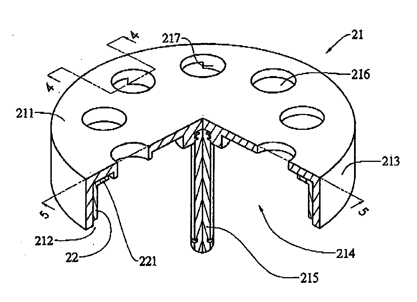
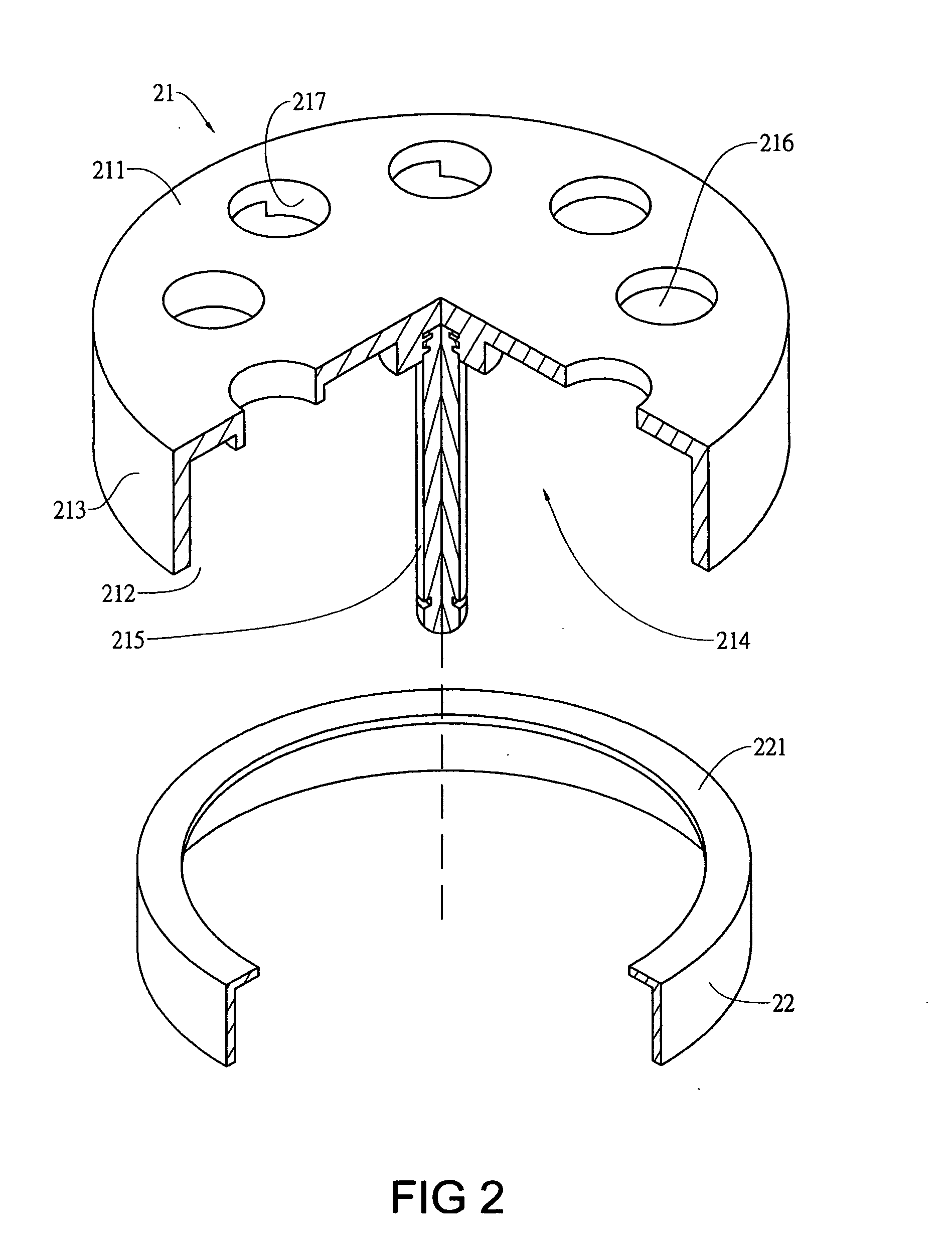
[0044] Referring to FIGS. 2 to 6, the first embodiment of a rotor device capable of forcing heat dissipation according to the present invention is illustrated. The rotor device in the first embodiment comprises a hub 21 and an inner casing 22 disposed in the hub 21. The hub 21 has a closed end 211 and an open end 212 and a circumferential wall 213 is disposed between and connected to the two ends 211, 212 with a semi-closed receiving room 214 being formed. A shaft 215 is joined to the center of the hub 21. The closed end 211 has at least a radial through hole 216 with at least a projection extending inward from the inner surface of the closed end 211 along the circumference of the through hole 216 as shown in FIGS. 4, 5 and 6. The inner casing 22 is attached to the inner side of the circumferential wall 213 with a lip 221 thereof closely contacting with the closed end 211. Further, the inner casing 22 and the hub 21 are bonded with adhesives.

[0045] Referring to FIGS. 2, 7, 8, 9 and...

Example

[0047] Referring to FIGS. 14 to 22, the second embodiment of the present invention is illustrated. The entire structure of the second embodiment is about the same as the preceding embodiment so that the identical parts are designated as the same reference numbers and no detail will be described further. The difference of the second embodiment is in that the projections 317 are disposed at the outer surface of the closed end 211 as shown in FIG. 21. When the hub 21 and the inner casing 22 rotate along the direction of arrow “B”, i.e., direction toward right side of the figure, the projections 317 provides a function of guiding flow to allow fluid at the top of the through holes 216 moving toward left side of the figure. Meanwhile, the fluid in the receiving room 214 moves upward via the through holes 216 instead and then moves to the left of the figure such that the fluid flows continuously with this way and temperature rose fluid in the receiving room 214 flows outward. When the hub...

Example

[0048] Referring to FIGS. 23 to 31, the third embodiment of the present invention is illustrated. The entire structure of the second embodiment is about the same as the preceding embodiment so that the identical parts are designated as the same reference numbers and no detail will be described further. The difference of the second embodiment is in that the projections 417a, 417b are disposed at the inner and the outer surfaces of the closed end 211 respectively and extend inward or outward along the circumferences of both ends of the through holes 216. When the hub 21 and the inner casing 22 rotate along direction of arrow D as shown in FIG. 30, i.e., right side of FIG. 30, the projections 417a at the outer surface of the closed end 211 can occur action of guiding flow to allow fluid at top of the through holes 216 moving to the left side of FIG. 30 and projections 417b at the inner surface of the through holes 216 are inversely tangent to the fluid in the receiving room 214, that i...


PUM


Abstract

A rotor device capable of forcing heat dissipation includes a hub and an inner casing. The hub provides a closed end with at least a through hole radially disposed thereon and a projection extending therefrom along the circumference of the through hole. The inner casing is disposed in the hub. Fluid is forced by the projection to move outward or inward via the through hole so that temperature of the fluid in the hub and the inner casing can be lowered down.

Description

BACKGROUND OF THE INVENTION [0001] 1. Field of the Invention [0002] The present invention is related to a rotor device capable of forcing heat dissipation and particularly to a device to force heat generated during the rotor rotating. [0003] 2. Brief Description of the Related Art [0004] Referring to FIG. 1, a conventional rotor assembly of a fan motor includes a fan frame 11 and a hub 12. The fan frame 11 provides a support base 111 with a collar bush 112. A bearing 113 is received in the collar bush 112 and a stator 13 is disposed to surround and fit with the collar bush 112 such that the stator 13 can be attached to the support base 111. The hub 12 has main wall and a circumferential wall such that a space can be defined to receive a shield member 14. The shield member 14 also has a main wall and a circumferential wall to define a space for receive a rotor 15. A plurality of fan blades 121 are radially disposed outside the hub 12 and a spindle 16 is joined to the hub 12 and the s...

Claims


Application Information

Patent Timeline
IPC IPC(8): H02K9/00H02K9/06
CPCH02K1/2786H02K5/20H02K9/06F04D25/0613F04D25/082F04D29/329H02K5/207F04D29/5806H02K1/2791
Inventor LEE, MING-CHE
Owner ASIA VITAL COMPONENTS SHENZHEN CO LTD
Why Eureka
Try Eureka