Projector, method of controlling the projector, program for controlling the projector, and recording medium storing the program

a projector and projector technology, applied in the field of projectors, can solve the problems of not being convenient to use, the overall system of the projector becomes bigger,

Inactive Publication Date: 2006-08-17
SEIKO EPSON CORP
View PDF1 Cites 64 Cited by
  • Summary
  • Abstract
  • Description
  • Claims
  • Application Information

AI Technical Summary

Benefits of technology

[0023] The above-described effect can be achieved by applying, to the projector of the invention, the method of controlling the projector, the program for controlling the projector, and the recording medium storing the program.

Problems solved by technology

Accordingly, there has been a problem in that an overall system of a projector becomes bigger and it is not convenient to be used.

Method used


Image

  • Projector, method of controlling the projector, program for controlling the projector, and recording medium storing the program
  • Projector, method of controlling the projector, program for controlling the projector, and recording medium storing the program
  • Projector, method of controlling the projector, program for controlling the projector, and recording medium storing the program

Examples


embodiment

Effect of Embodiment

[0124] The above-described embodiment have the following effect.

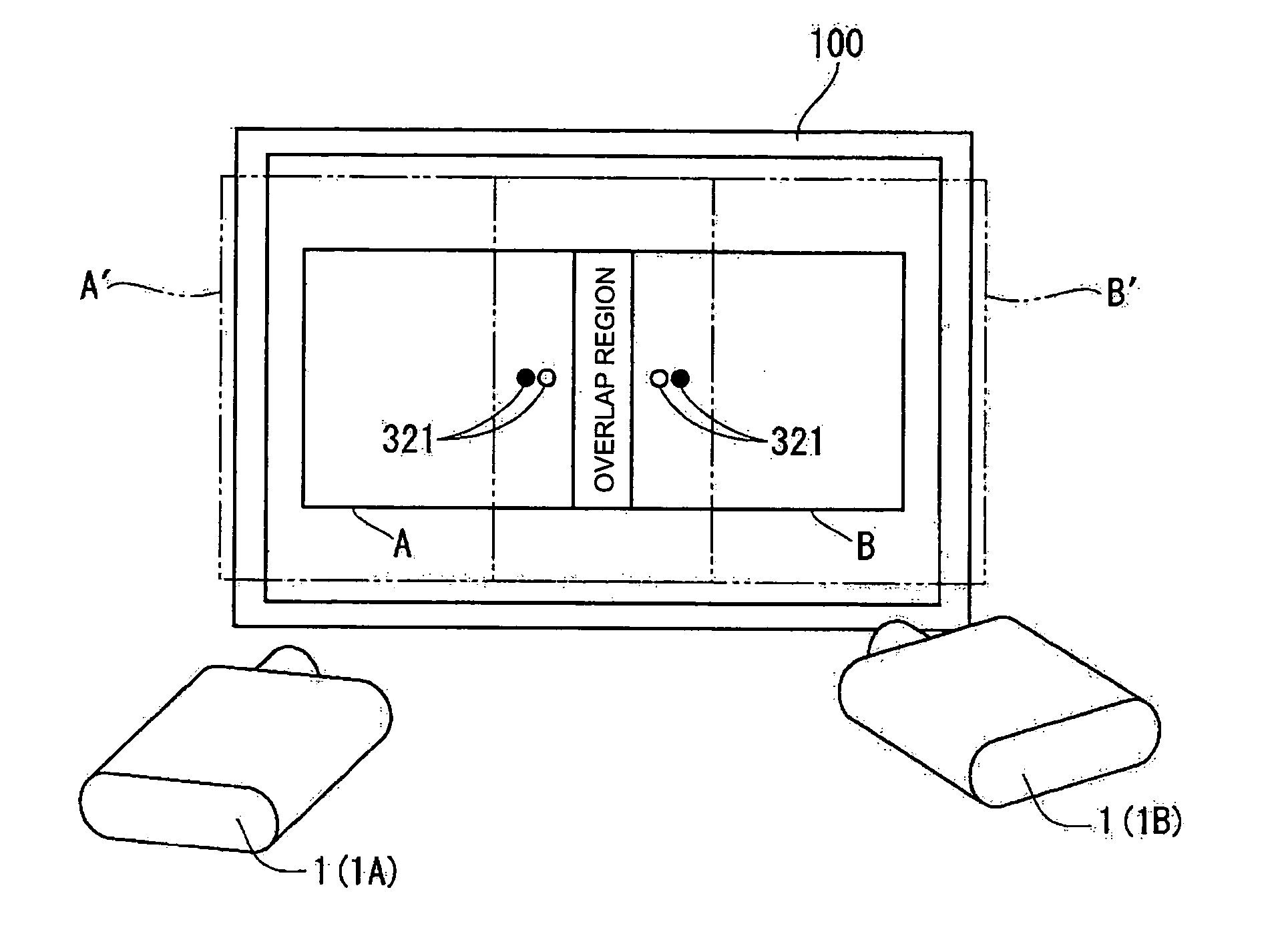
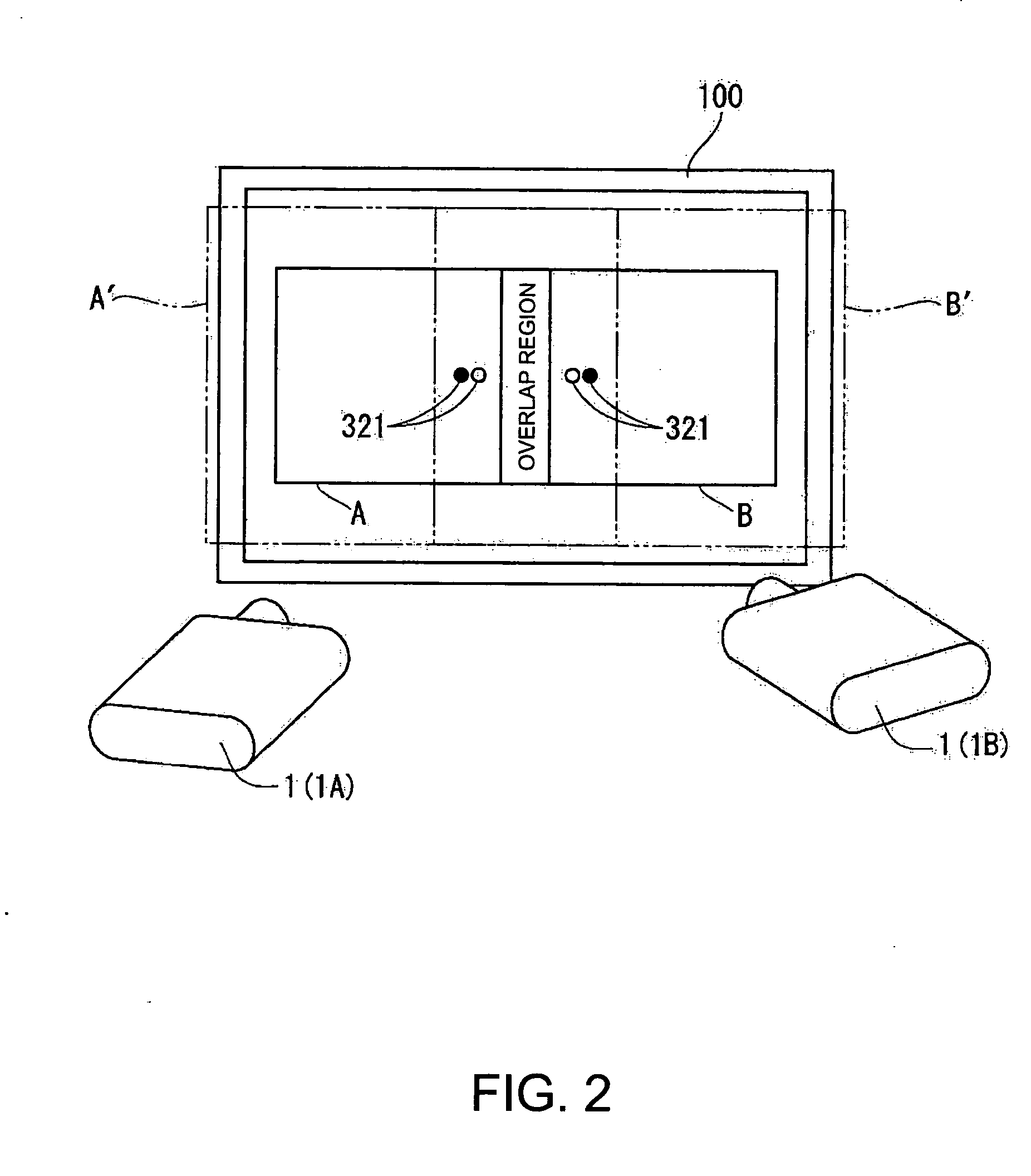
[0125] (1) When the projector 1, which projects the image by the stand-alone mode or tiling mode, performs the tiling projection by adding a new projector 1, both closing projectors 1 display the projection position information transmitting pattern 311, capture the projection position information transmitting pattern 311 projected by the other party, and recognize that both projectors 1 try to perform the tiling projection. Accordingly, it does not need that a dedicated control unit according to the related art transmits information for performing the tiling projection and the tiling projection can be performed without the control unit. Further, it is possible to perform the tiling projection without troublesome when setting the tiling projection.

[0126] (2) The projection position information transmitting pattern 311 is not only for transmitting that the tiling projection is ready to perform but al...


PUM


Abstract

A projector includes an image capture device that captures an image in a capture region larger than a projection region of a projection image; an image determining unit that compares and determines the projection image projected by the corresponding projector with another projection image projected in the capture region on the basis of capture information acquired from the image capture device; a transmission image display unit that projects and displays a transmission image indicating that the corresponding projector is ready to perform a tiling projection when the image determining unit determines that the projection image projected by the corresponding projector is the same as the another projection image; a transmission image determining unit that determines whether or not another projector projecting the another projection image has projected the transmission image; and a process parameter creating unit that creates a process parameter which processes display information of the projection image on the basis of a determination result of the transmission image determining unit.

Description

BACKGROUND [0001] 1. Technical Field [0002] The present invention is related to a projector, a method of controlling the projector, a program for controlling the projector, and a recording medium storing the program. [0003] 2. Related Art [0004] A projection type projector can easily arrange or overlap images (still images or motion pictures) on a screen, as compared with a display device, such as a CRT display or a liquid crystal display called as a direct-view-type display. In other words, it is possible to obtain large and high-definition projection images by projecting images output from a plurality of projectors on the screen so as to be parallel to one another (called as tiling projection or division projection: refer to JP-A-2001-51346 and JP-A-2004-32665), and it is also possible to obtain even brighter projection images by projecting the images on the screen so as to overlap one another (called as stacking or overlapping projection). [0005] In recent years, as a research of...

Claims


Application Information

Patent Timeline
Patent Type & Authority Applications(United States)
IPC IPC(8): G03B21/14
CPCG03B37/04H04N9/3147H04N9/3194H04N9/3197
Inventor HASEGAWA, HIROSHI
Owner SEIKO EPSON CORP
Why Eureka
Try Eureka