Tuning a laser

Inactive Publication Date: 2006-08-17
AGILENT TECH INC
View PDF7 Cites 6 Cited by
  • Summary
  • Abstract
  • Description
  • Claims
  • Application Information

AI Technical Summary

Problems solved by technology

The mechanical tolerance of the pivot position in the mechanically tuned lasers could be on the order of 1 μm or less and achieving this tolerance is expensive.
However, being able to compensate for errors in the pivot location is only part of the problem.
A disadvantage of this technique is that it requires a complete and accurate model of the laser.
This is difficult to achieve in practice, especially as the laser's behavior may not be time invariant.

Method used


Image

  • Tuning a laser
  • Tuning a laser
  • Tuning a laser

Examples


Embodiment Construction

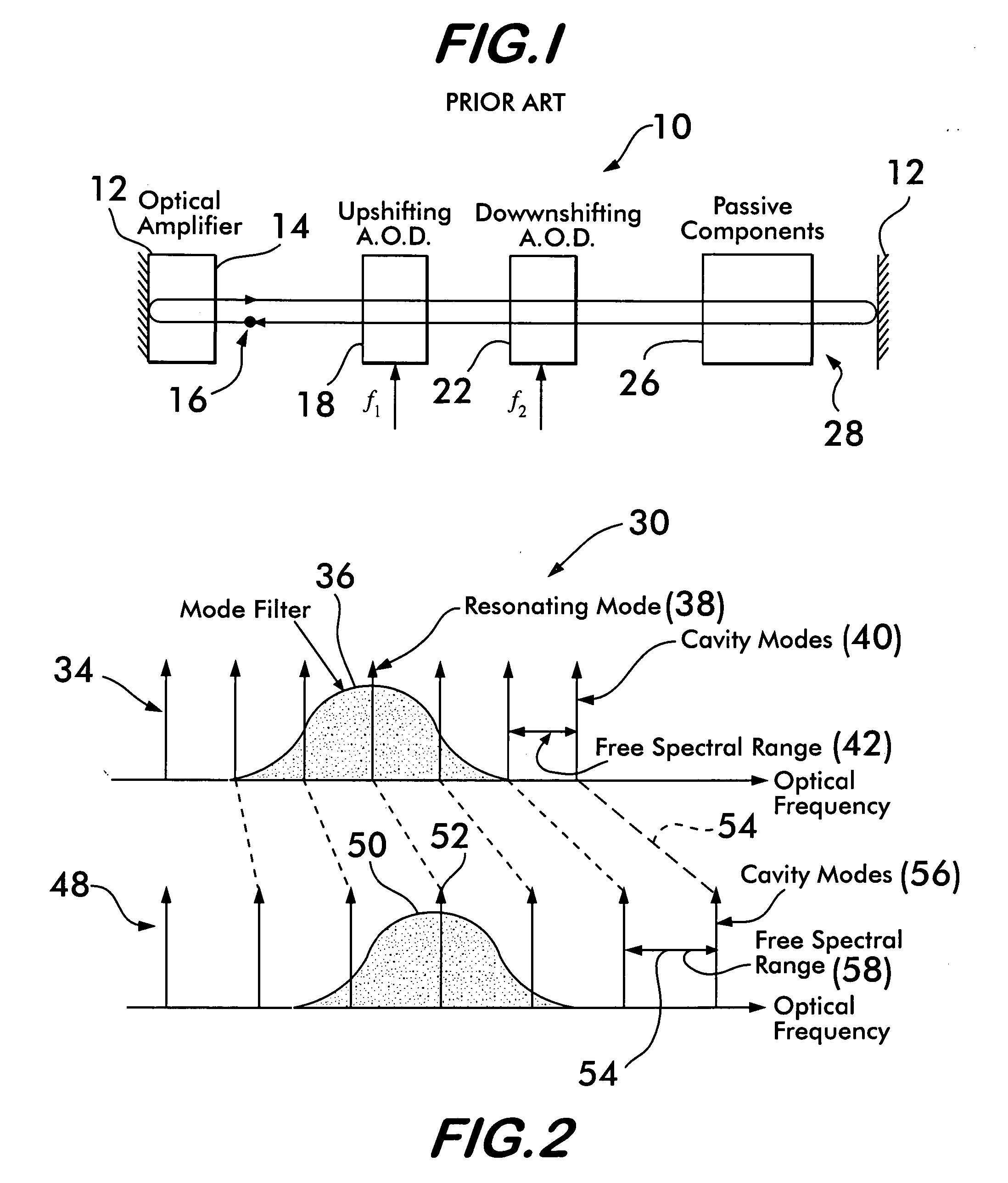
[0014] Referring now to FIG. 1, there is shown a schematic representation of a prior art acousto-optically tuned external cavity laser system 10, wherein the mirrors 12 define the cavity 28 of the laser system 10. The cavity 28 of the acousto-optically tuned external cavity laser system 10 is adapted to permit the light beams 16 to bounce back and forth between the mirrors 12 when the external cavity laser system 10 is operating in its resonant mode. The cavity 28 of the external cavity laser system 10 also includes an upshifting acousto-optic device (A.O.D.) 18 and a downshifting A.O.D. 22 for frequency shifting the light beams 16. The types of acousto-optical devices used in a particular laser design could include, but not be limited to deflectors, filters, modulators, or combinations of these types.

[0015] When the upshifting A.O.D. 18 and the downshifting A.O.D. 22 frequency shift the light beams 16 they change the resonant modes within the external cavity laser system 10 by all...


PUM


Abstract

A method for synchronously tuning a laser in a laser system having a set of possible resonant frequencies including a resonating mode resonant frequency, an optical amplifier with an optical gain and a mode filter having a center frequency includes the steps of determining the optical gain of the optical amplifier and providing an optical gain signal representative of the optical gain. An apparatus for synchronously tuning a laser in a laser system has a set of possible resonant frequencies including a resonating mode resonant frequency and a mode filter having a pass band with a center frequency. The apparatus has an optical amplifier having an optical gain and a frequency shifter. The frequency shifter shifts the center frequency of the pass band in accordance with the optical gain to move the center frequency of the pass band toward the resonating mode resonant frequency.

Description

BACKGROUND OF THE INVENTION [0001] In order to tune a laser in a single mode without mode hops, the cavity and the mode selecting filter of the laser must be tuned synchronously. In the known art of mechanical tuning of lasers, synchronous tuning ranges of many tens of nanometers of wavelength could be achieved by rotating a cavity mirror or diffraction grating about a specific pivot point. Only one location of the pivot point provided synchronous tuning of the lasers. The Littman and Littrow configurations are well known examples of this type of mechanically tuned lasers. [0002] The mechanical tolerance of the pivot position in the mechanically tuned lasers could be on the order of 1 μm or less and achieving this tolerance is expensive. Furthermore, the location of the pivot point may vary with temperature and air pressure. It may also vary slightly with oscillation wavelength. For these reasons, it would be attractive to be able to adjust lasers for synchronicity without physicall...

Claims


Application Information

Patent Timeline
IPC IPC(8): H01S3/10H01S3/098
CPCH01S3/1068H01S3/137H01S5/14
Inventor OWEN, GERAINTTRUTNA, WILLIAM R. JR.
Owner AGILENT TECH INC
Why Eureka
Try Eureka