
Method and apparatus for masking of video artifacts and/or insertion of film grain in a video decoder

a video artifact and video decoding technology, applied in the field of compressed video, can solve the problems of visual masking (or hiding) other video artifacts, noise storage, and the use of expensive on-chip memory in storag

Active Publication Date: 2006-08-17
AVAGO TECH INT SALES PTE LTD
View PDF10 Cites 49 Cited by
  • Summary
  • Abstract
  • Description
  • Claims
  • Application Information

AI Technical Summary

Benefits of technology

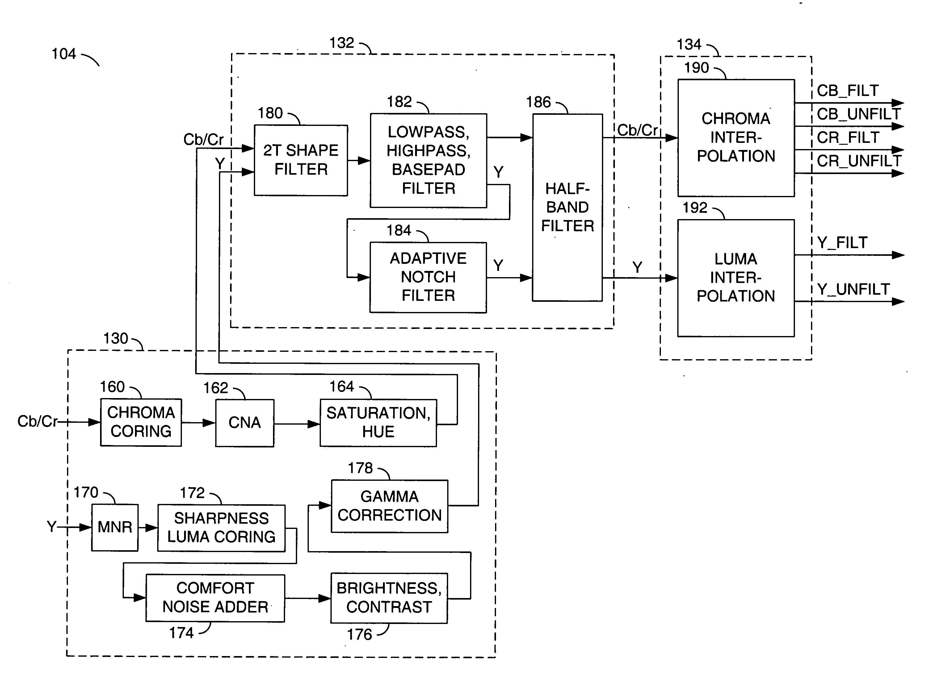
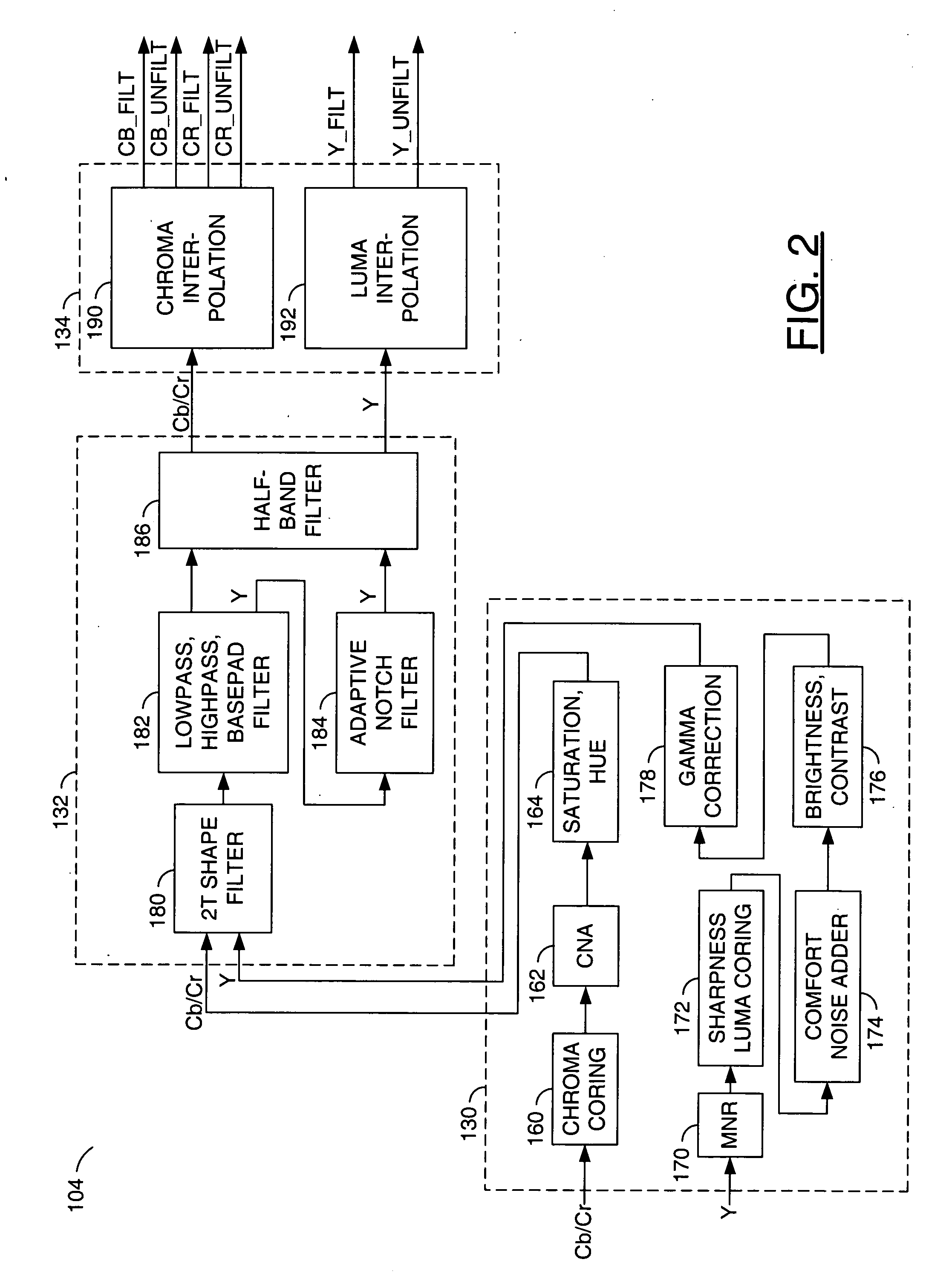
[0008] The present invention concerns a video decoder comprising (i) a post-processing filter block, (ii) a comfort noise addition block and (iii) a video value/range adjustment block, where the comfort noise addition block is integrated into a video output path of the video decoder. The post-processing filter block may be configured to perform one or more of noise reduction, spatial filtering and temporal filtering on luminance data. The comfort noise addition block may be configured to add comfort noise to the luminance data. The video value/range adjustment block may be configured to adjust one or both of a value and a range of the luminance data.
[0009] The objects, features and advantages of the present invention include providing a method and apparatus for masking of video artifacts and/or insertion of film grain in a video decoder that may (i) add nois

Problems solved by technology

Random noise can visually mask (or hide) other video artifacts.
The problem with pre-generated noise is storage.
For HD video rates, storage commonly uses expensive on-chip memories in order to meet the high video rates.
Conventional solutions do not integrate the noise addition into the video output path of a compressed video decoder.
This cannot be accomplished without noise addition that is integrated into the video output path of the compressed video decoder.

Method used


Image

  • Method and apparatus for masking of video artifacts and/or insertion of film grain in a video decoder
  • Method and apparatus for masking of video artifacts and/or insertion of film grain in a video decoder
  • Method and apparatus for masking of video artifacts and/or insertion of film grain in a video decoder

Examples


Embodiment Construction

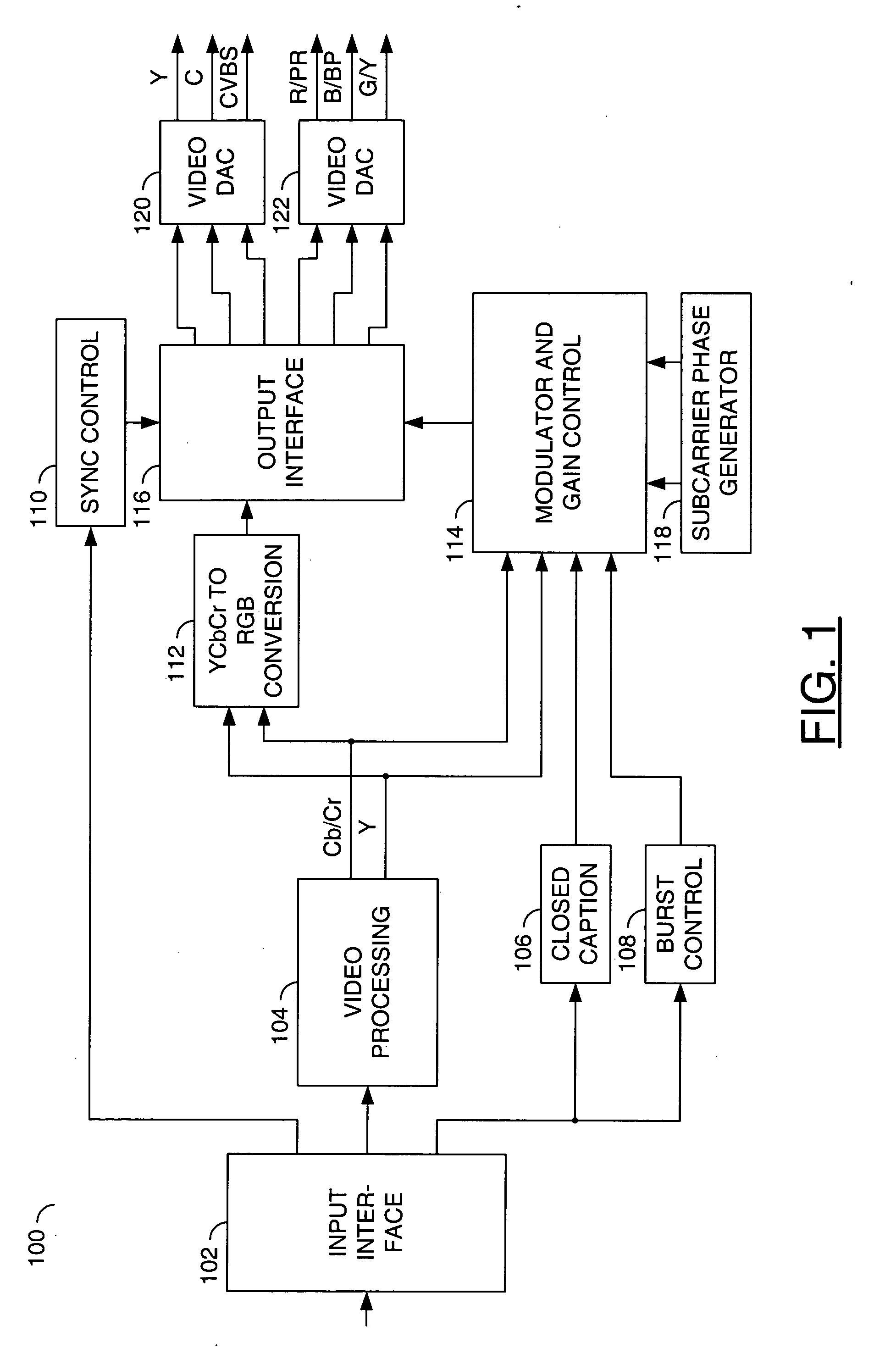
[0015] Referring to FIG. 1, a block diagram of a circuit 100 is shown in accordance with one or more preferred embodiments of the present invention. The circuit 100 may be implemented as part of an output path of a video decoder (e.g., a DVD player, MPEG-2 decoder, etc.). The circuit 100 may be implemented, in one example, as a digital video encoder / converter circuit (or block). The circuit 100 may be configured to convert a digital video input data stream into a NTSC or PAL composite or component video output. In one example, a digital input format may include 8-bit (interleaved) or 16-bit YCbCr 4:2:2 video. The circuit 100 may be configured to demultiplex, scale and filter both luminance (also referred to as luma or Y) and chrominance (also referred to as chroma, Cb and Cr components, or U and V components) samples. The circuit 100 may be further configured, in one example, to upsample to 54 MHZ, where the color information may be modulated onto a sub-carrier. The circuit 100 may ...


PUM


Abstract

A video decoder comprising (i) a post-processing filter block, (ii) a comfort noise addition block and (iii) a video value / range adjustment block, where the comfort noise addition block is integrated into a video output path of the video decoder. The post-processing filter block may be configured to perform one or more of noise reduction, spatial filtering and temporal filtering on luminance data. The comfort noise addition block may be configured to add comfort noise to the luminance data. The video value / range adjustment block may be configured to adjust one or both of a value and a range of the luminance data.

Description

FIELD OF THE INVENTION [0001] The present invention relates to compressed video generally and, more particularly, to a method and apparatus for masking of video artifacts and / or insertion of film grain in a video decoder. BACKGROUND OF THE INVENTION [0002] Numerous types of spatial and temporal artifacts are characteristic of transform compressed digital video (i.e., MPEG-2, MPEG-4, VC-1, WM9, DIVX, etc.). Artifacts can include contouring (particularly noticeable in smooth luminance or chrominance regions), blockiness, mosquito noise, motion compensation and prediction artifacts, temporal beating, etc. [0003] Less structured (or “random” noise) is more characteristic of analog video, which is familiar to consumers through broadcast TV (cable or terrestrial), VHS / PAL video cassette playback, and film grain. In fact, film producers may desire the “look and feel” of particular film grain artifacts as a very noticeable artistic effect. Even when random noise is not desirable as an artis...

Claims


Application Information

Patent Timeline
IPC IPC(8): H04B1/66
CPCG06T2207/20204H04N19/61H04N19/44G06T2207/10024G06T5/002G06T5/009G06T2207/10016H04N19/86G06T5/92G06T5/70
Inventor WINGER, LOWELL L.
Owner AVAGO TECH INT SALES PTE LTD
Learn More