Radio integrated circuit

Inactive Publication Date: 2006-08-17
LAPIS SEMICON CO LTD
View PDF5 Cites 9 Cited by
  • Summary
  • Abstract
  • Description
  • Claims
  • Application Information

AI Technical Summary

Benefits of technology

[0034] It is an object of the present invention to provide a radio LSI that can send acknowledgement data without a delay by increasing the rate of reception data control.
[0037] The invention has, in the sending / receiving section, the first holding part that monitors reception data being received and holds it when frame control information is received, and the decoding part that decodes a data length and structure of address field depending upon the information held. This makes it possible to know a field representative of a source address during receiving data. Furthermore, because of the provision of the comparing part that compares an address represented in the addressing field with an address registered in the registering part, it can be determined, during reception, whether or not there is data to be sent to the source. Accordingly, there is an effect that the data-link section is allowed to send acknowledgement data without encountering a delay.

Problems solved by technology

However, the reception circuit involves the following problem.

Method used


Image

  • Radio integrated circuit
  • Radio integrated circuit
  • Radio integrated circuit

Examples


first embodiment

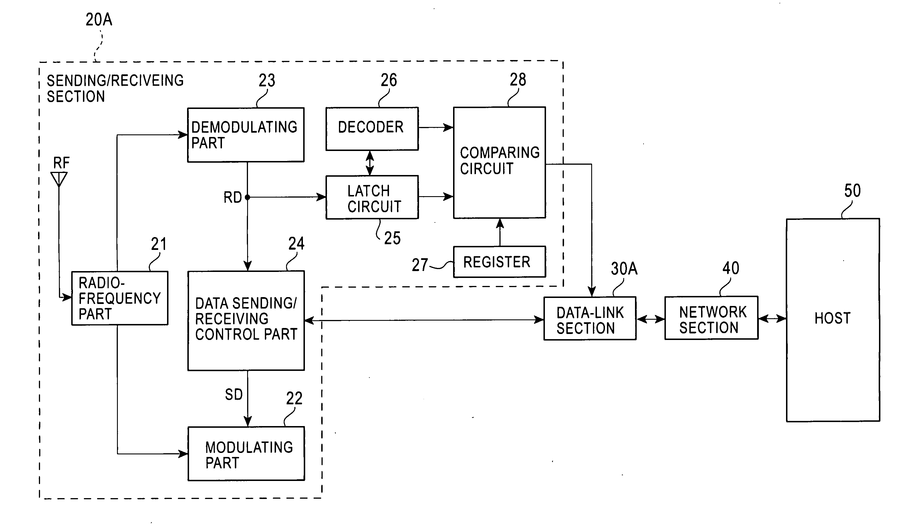
[0051]FIG. 8 is a schematic functional block diagram of a radio LSI showing the present invention.

[0052] The radio LSI is compatible with ZigBee, a standard for near-distance radio communication technology. This LSI is made in an IC-chip including a transmitting-receiving section 20A as a hardware realizing a physical layer to perform data transmission and reception on a radio-frequency signal RF, a data-link section 30A having a MAC processing part, etc. to send and receive data through the transmitting-receiving section 20A and for realizing a processing in the data-link layer, and a network section 40 for transferring data with a host 50, and so on.

[0053] The transmitting-receiving section 20A has a radio-frequency part 21 for sending and receiving a 2.4-GHz-band radio-frequency signal RF through an antenna built-in or separately arranged, a modulating part 22 for modulating transmission data SD into an O-QPSK (offset orthogonal phase shift keying) signal and supplying it to the...

second embodiment

[0068]FIG. 11 is a schematic functional block diagram of a radio LSI showing the invention. The common elements to those of FIG. 8 are attached with the common references.

[0069] The radio LSI is provided with a transmitting-receiving section 20B and data-link section 30B somewhat different in function, in place of the transmitting-receiving section 20A and data-link section 30A of FIG. 8.

[0070] The transmitting-receiving section 20B has interrupt control means (e.g. interrupt control circuit) 29 in place of the register 27 and comparing circuit 28 of the transmitting-receiving section 20A. The interrupt control circuit 29 is to make an interruption to the data-link section 30B when fixed is the data in the address field of the reception data RD, and notify the address-field data to the MAC processing part of the data-link section 30B.

[0071] Meanwhile, the data-link section 30B is added with a function that, when detecting an interruption from the interrupt control circuit 29, addr...


PUM


Abstract

A radio LSI is provided that is not to cause a delay in sending acknowledgement data. A latch circuit provided in a sending / receiving section latches frame control information out of data being received. A decoder decodes the frame control information to decode a data length and structure of an address field. Furthermore, a latch circuit latches the address-field data of the reception data according to the decoded address-field information. A comparing circuit compares a content of a register entered with an address of the opposite-of-communication completely prepared data to be sent, with a source address of the data being received, to determine a setting / resetting of frame pending in acknowledgement data. A content of the determination is sent to a data-link section. This provides information required for acknowledgement data before completely receiving data, thus eliminating the possibility to cause a delay in sending acknowledgement data.

Description

BACKGROUND OF THE INVENTION [0001] 1. Field of the Invention [0002] The present invention relates to a radio integrated circuit (hereinafter, referred to as “radio LSI”) compatible with ZigBee (ZigBee Alliance's registered trademark), one of the near-distance radio communication technology standards that the physical layer interface conforms to IEEE (Institute of Electrical and Electronic Engineers) 802.15.4 and the 2.4 GHz frequency band, similar to IEEE 802.11b of the radio LAN (local area network) standard, is utilized by segmented into 16 channels, and more particularly to a technique for controlling the reception data thereof. [0003] 2. Description of the Related Art [0004]FIG. 1 shows a communication hierarchical model of ZigBee. [0005] The lowermost physical layer 1, for sending / receiving actual data, defines an applicable radio frequency, modulation scheme, data rate and the like. A data-link layer 2, for sending / receiving data through the physical layer 1, has a media acces...

Claims


Application Information

Patent Timeline
Patent Type & Authority Applications(United States)
IPC IPC(8): H04L27/00
CPCH04L1/1607
Inventor SATO, SHIGEYUKI
Owner LAPIS SEMICON CO LTD
Why Eureka
Try Eureka