Carriage system

Active Publication Date: 2006-08-17
MURATA MASCH LTD
View PDF13 Cites 51 Cited by
  • Summary
  • Abstract
  • Description
  • Claims
  • Application Information

AI Technical Summary

Benefits of technology

[0010] According to the present invention, for facilities such as inspection devices which have a high throughput, the second carriage transfers articles between the facilities and the buffers. The first carriage transfers articles between the buffers and other facilities. By locally placing the carriage for the facilities with a high throughput, it is possible to locally improve the conveying capability.
[0011] Compared to the case in which a circulating conveyor is connected to the load port of the facility, the present invention eliminates the need to move all the articles on the conveyor. It is only necessary that the second carriage move only the required articles between the facility and the buffer. This simplifies the facilities and makes it possible to keep articles precisely positioned. The above description is not intended to exclude the provision of the conveyor for the buffer.
[0012] According to the aspect of the present invention set forth in Claim 2, the buffer is provided below the running rail for the

Problems solved by technology

Such a buffer improves conveyance efficiency but is in

Method used


Image

  • Carriage system
  • Carriage system
  • Carriage system

Examples


Example

[0020] A description will be given below of an optimum embodiment for carrying out the present invention.

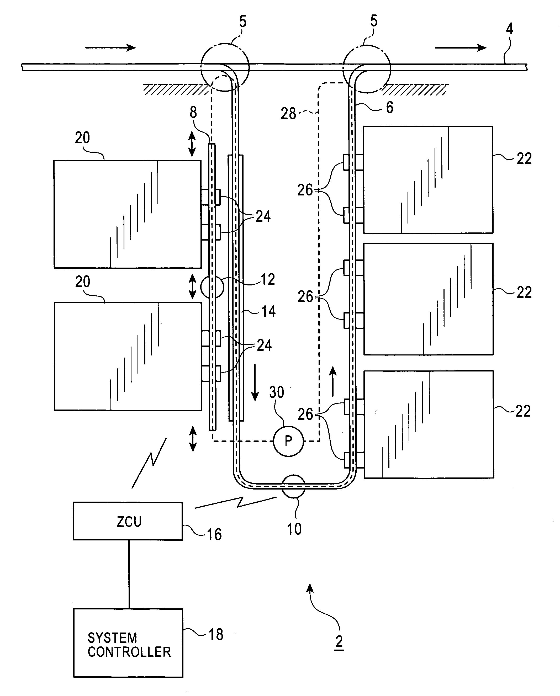
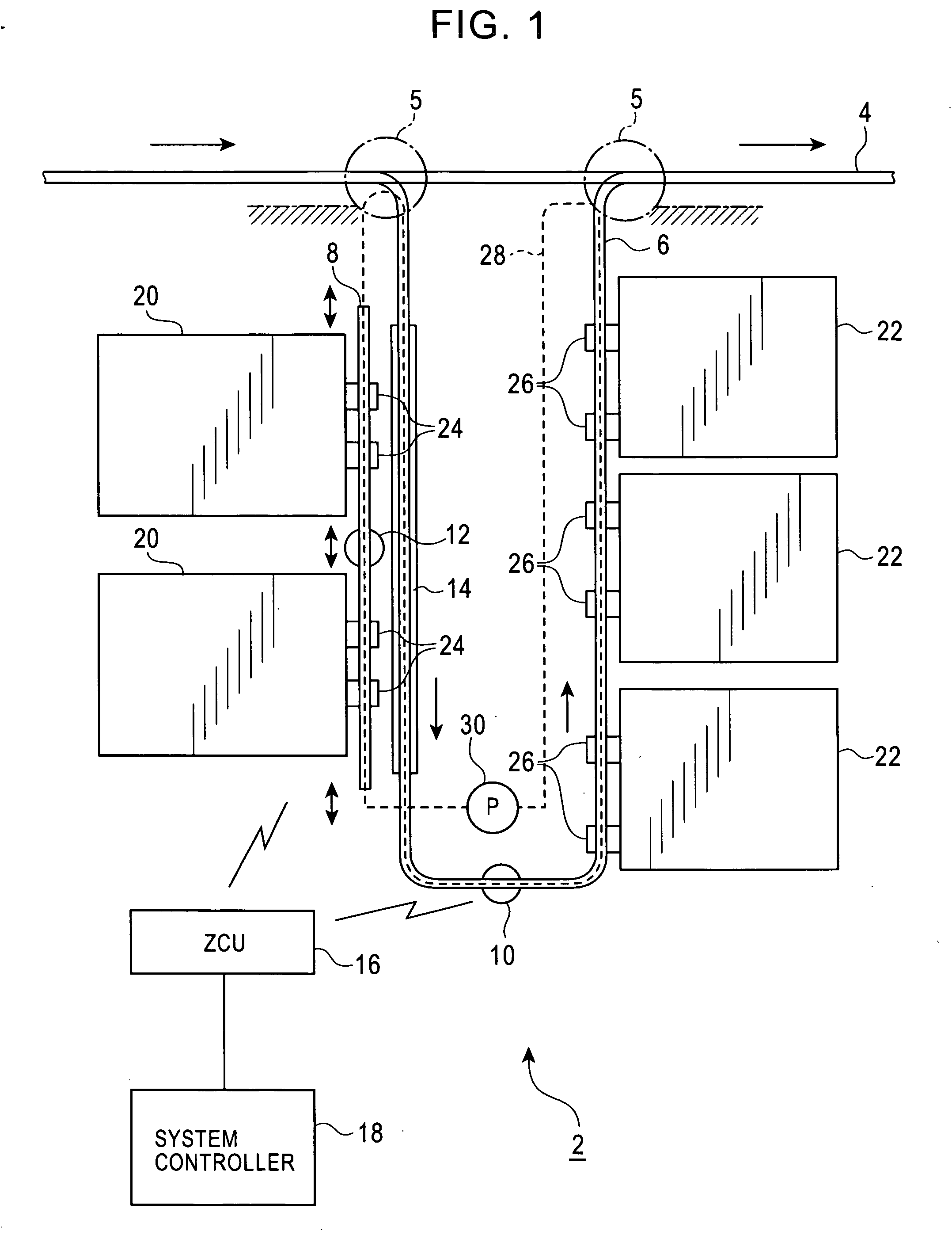
[0021] FIGS. 1 to 6 show embodiments and a variation. In these figures, 2 is an overhead vehicle system comprising an inter-bay route 4 constituting an infrastructure and an intra-bay route 6 for each bay. 5 is a branching and joining portion located between the inter-bay route 4 and the intra-bay route 6. The inter-bay route 4 or the intra-bay route 6 is an example of a first running route. A local route 8 is provided near facilities requiring a high conveying capability so as to lie parallel to the intra-bay route 6. The local route 8 is an example of a second running route. 10 is an overhead vehicle running on the inter-bay route 4 or the intra-bay route 6. The overhead vehicle 10 is an example of a first carriage. 12 is an overhead vehicle that for example, reciprocates on the local route 8. The overhead vehicle 12 is an example of a second carriage. 14 is a buffer provided ...


PUM


Abstract

A running rail 9 and a second overhead vehicle 12 are arranged parallel to a running rail 7 for a first overhead vehicle 10 and closer to inspection devices 20 than the running rail 7. A buffer 14 is provided below the running rail 7. The overhead vehicle 12 conveys a cassette 40 between load ports 24 and the buffer 14. The overhead vehicle 10 conveys the cassette 40 between the buffer 14 and other positions. The present invention can deal with inspection devices or the like which have a high throughput by locally improving their conveying capability.

Description

FIELD OF THE INVENTION [0001] The present invention relates to a system using a carriage such as an overhead vehicle or a rail-guided carriage, and in particular, to improvement of throughput. BACKGROUND OF THE INVENTION [0002] In connection with conveyance of articles in semiconductor plants or the like, facilities such as inspection devices must process a large number wafers or the like per a unit time (these facilities have a high throughput). Accordingly, compared to the other facilities, these facilities must enhance their conveying capabilities locally, for example, around inspection devices. To locally enhance the conveying capability, it is preferable to provide random-access buffers. In an easily conceivable example, a circulating conveyor is connected to load ports of the inspection devices so that articles can be freely transferred between a carriage and a plurality of positions on the conveyor. However, to precisely transfer articles to and from the carriage, such a conv...

Claims


Application Information

Patent Timeline
IPC IPC(8): B65G1/00
CPCB65G47/5104B65G47/52B65G47/61B65G2201/0297Y10S414/14
Inventor YAMAMOTO, MAKOTOHOSHINO, KENJI
Owner MURATA MASCH LTD
Why Eureka
Try Eureka