

Tungsten film forming method
- Summary
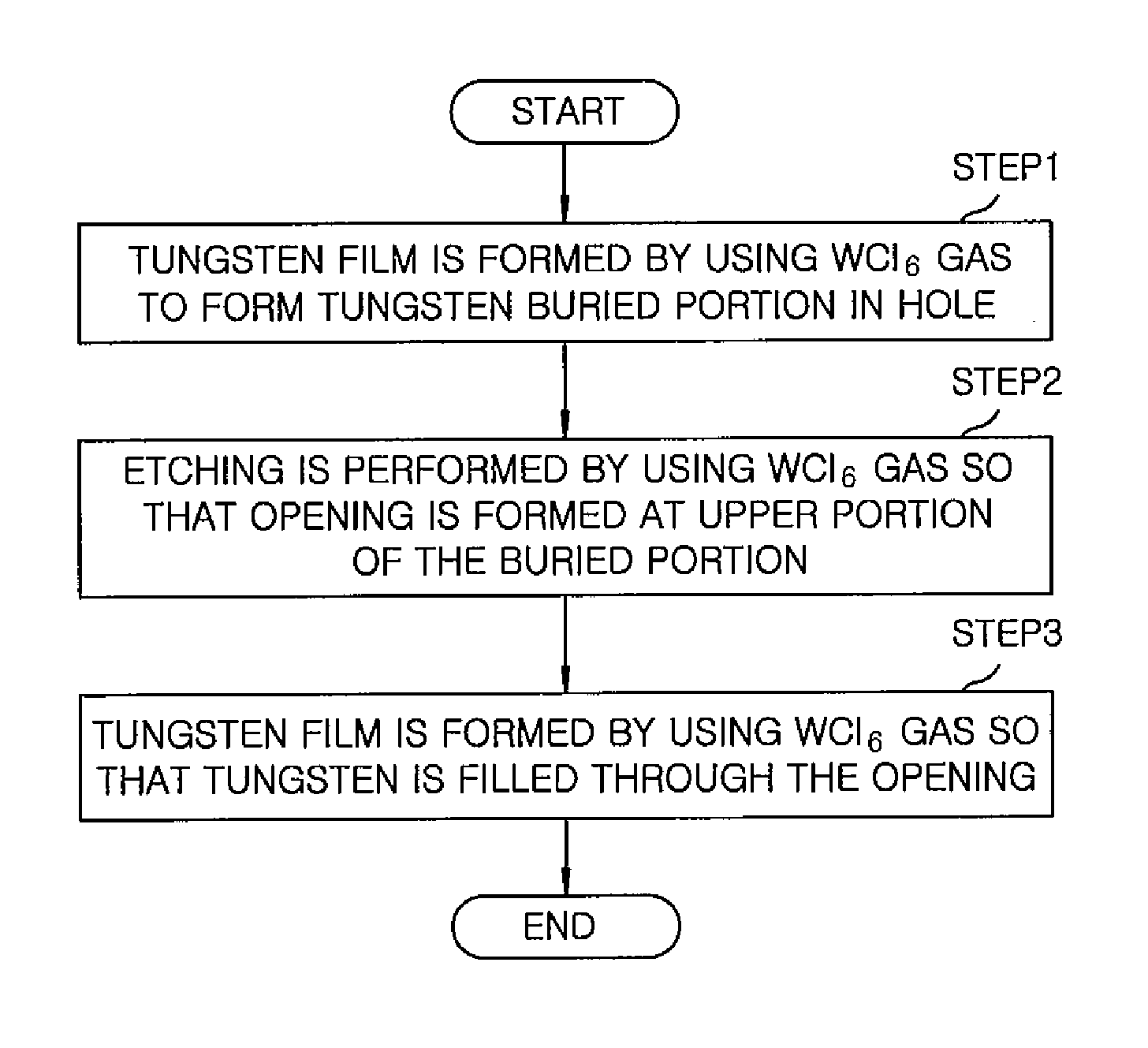
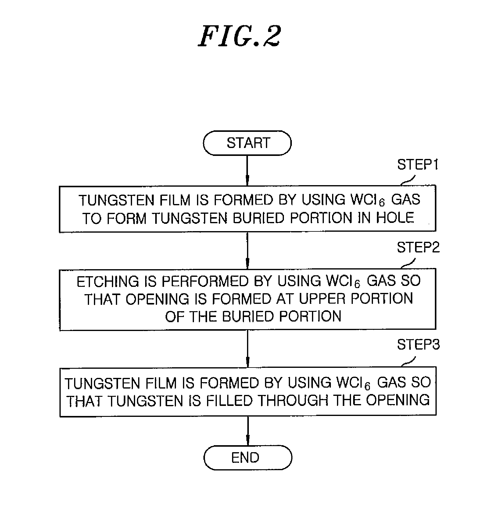
- Abstract
- Description
- Claims
- Application Information
AI Technical Summary
Benefits of technology
Problems solved by technology
Method used
Image

Examples
Embodiment Construction
[0027]Hereinafter, embodiments of the present invention will be described in detail with respect to the accompanying drawings.
[0028]
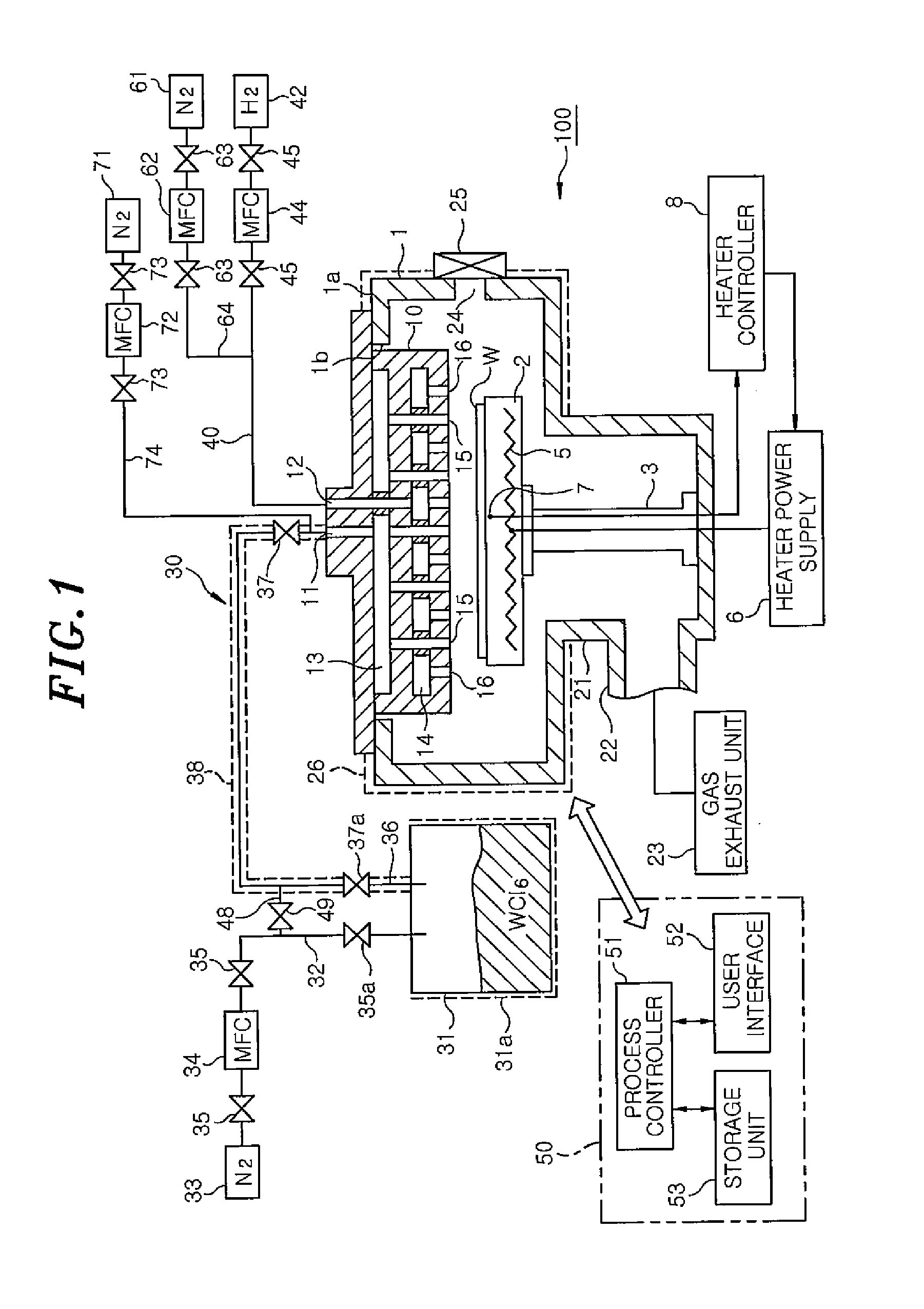
[0029]FIG. 1 is a cross sectional view showing an example of a film forming apparatus for implementing a tungsten film forming method in accordance with an embodiment of the present invention.
[0030]As shown in FIG. 1, a film forming apparatus 100 includes an airtight cylindrical chamber 1. In the chamber 1, a susceptor 2 for horizontally supporting a wafer W serving as a substrate to be processed is supported by a cylindrical supporting member 3 extending from a bottom portion of a gas exhaust chamber, which will be described later, to a lower central portion of the chamber 1. The susceptor 2 is made of ceramic, e.g., AlN or the like. A heater 5 is embeded in the susceptor 2. A heater power supply 6 is connected to the heater 5. A thermocouple 7 is provided near a top surface of the susceptor 2. A signal of the thermocouple 7 is transmitted to a heater ...
PUM
 Abstract
Description
Claims
Application Information