
Ultrasonic imaging apparatus

Inactive Publication Date: 2006-08-17
GE MEDICAL SYST GLOBAL TECH CO LLC
View PDF7 Cites 12 Cited by
  • Summary
  • Abstract
  • Description
  • Claims
  • Application Information

AI Technical Summary

Benefits of technology

[0009] Therefore, an object of the present invention is to provide an ultrasound imaging apparatus, which allows the morphological comparison of the measurement pattern set within a plurality of ultrasonic images to be done in a reliable and easier manner.
[0018] In the fifth aspect of the present invention, the pointing device is equiped for facilitating the cursor position control.
[0028] In accordance with the eleventh aspect of the present invention, the batch storage means facilitates to store a plurality of measurement patterns present in the ultrasonic image.
[0030] In accordance with twelfth aspect of the present invention, the batch reproduction means facilitates to reproduce a plurality of measurement patterns in an ultrasonic image.
[0032] In accordance with thirteenth aspect of the present invention, the magnification rate changer means allows the storage and reproduction to be performed across ultrasonic images of different display magnification rate.
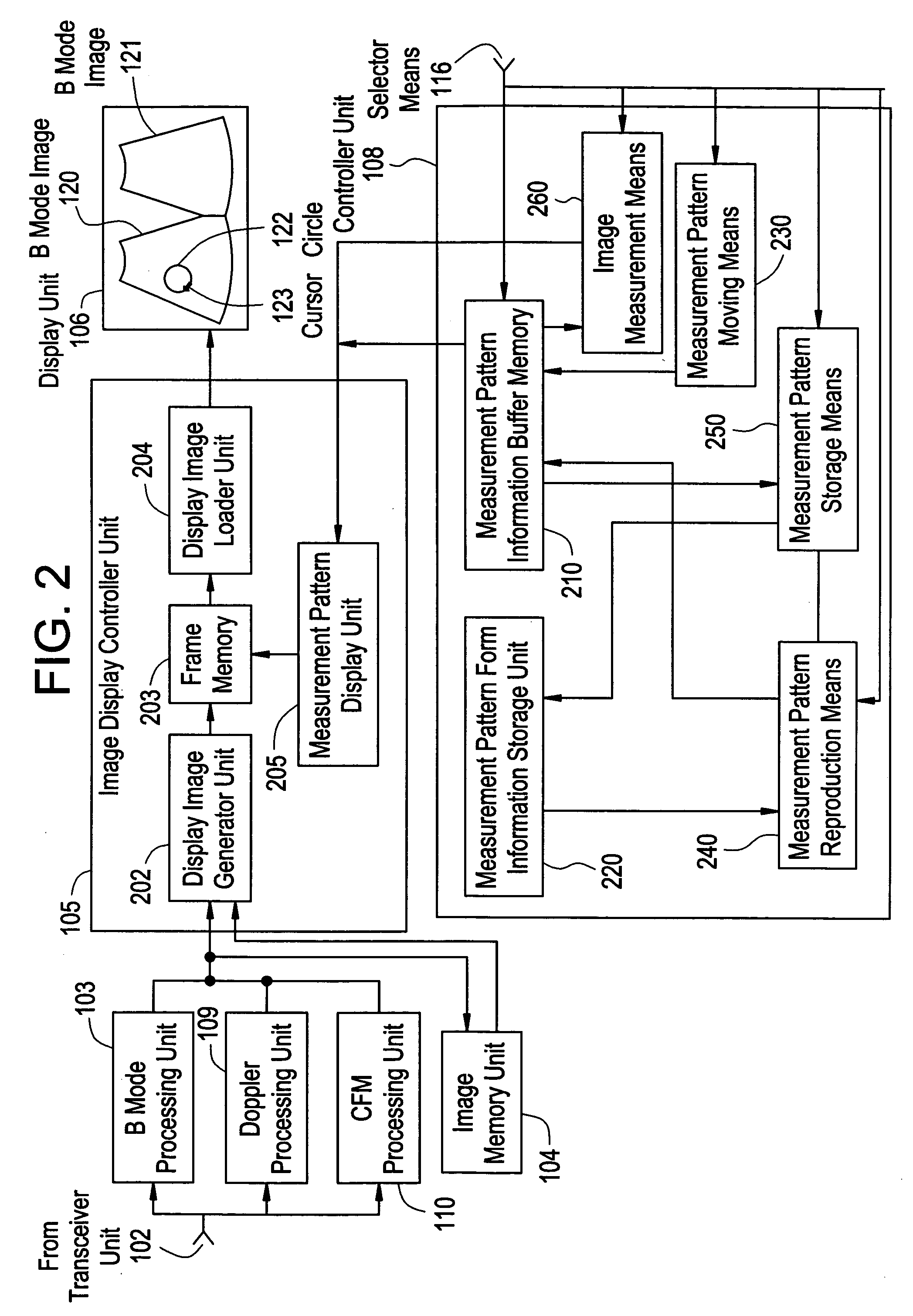
[0038] In accordance with the present invention, the selector means specifies the position within an ultrasonic image, and if any measurement pattern is present at the specified location, the measurement pattern storage means will store the morphological info of the measurement pattern, and the measurement pattern reproduction means will reproduce thus stored morphological information of the measurement pattern at the position to be specified later by means of the selector means into an ultrasonic image, so that when performing the image measurement of imaged site where the morphology changes along with time course to compare the morphologies, not only numerical data but also the measurement pattern that indicates the form of imaged site at various temporal phase can be superposed to compare between the morphologies visually and reliably, and ultimately leading to a proper examination of numerical data by the operator.

Problems solved by technology

In accordance with the prior art as have been described above, however, the data comparison using the measurement pattern can be done for the numerical data, and is neither instinctive nor visual.
On the other hand, when performing a visual comparison of anatomical morphologies of measurement pattern set to each image by appositing a plurality of ultrasonic images of an imaging location sequencing the dynamism, the morphological comparison between measurement patterns may become too ambiguous to achieve a reliable morphological comparison.

Method used


Image

  • Ultrasonic imaging apparatus
  • Ultrasonic imaging apparatus
  • Ultrasonic imaging apparatus

Examples


Embodiment Construction

[0048] The best mode for carrying out the ultrasonic imaging apparatus in accordance with the present invention will be described in greater details herein below with reference to the accompanying drawings. It should be noted here that the illustrated embodiment are intended not to limit the present invention.

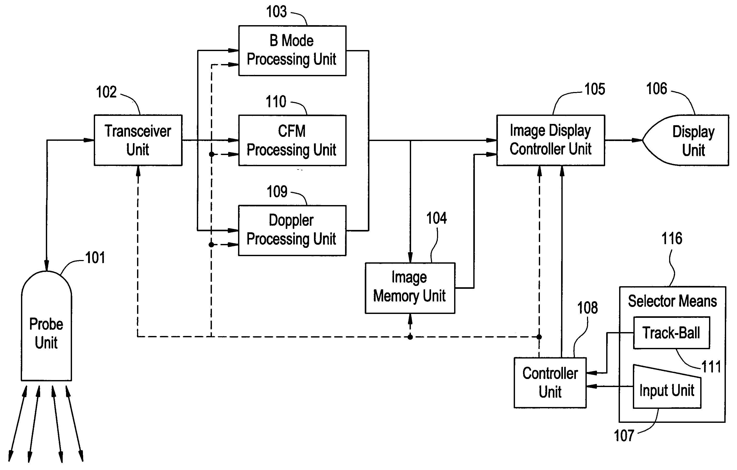
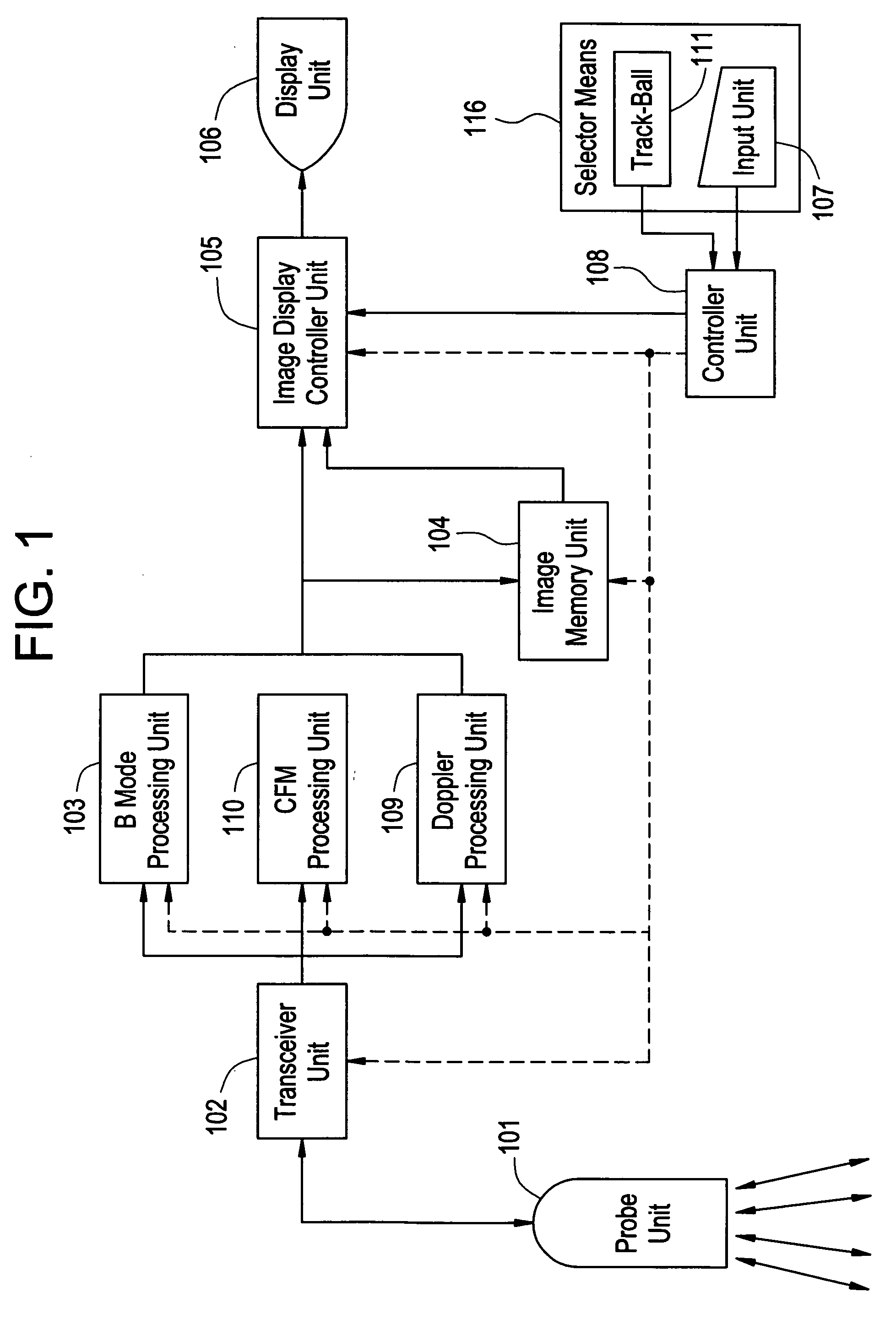
[0049]FIG. 1 shows a schematic block diagram indicative of the overview of ultrasonic imaging apparatus in accordance with a preferred embodiment of the present invention. The ultrasonic imaging apparatus has a probe 101, a transceiver unit 102, a B mode processing unit 103, a Doppler processing unit 109, a color flow mapping (CFM) processing unit 110, an image memory unit 104, an image display controller unit 105, a display unit 106, a selector means 116, and a controller unit 108. It is noted here that in FIG. 1 and FIG. 2 which will be described hereinbelow, the signal lines for carrying image information or selection information are indicated by solid lines, while the sign...


PUM


Abstract

An ultrasonic imaging apparatus which displays ultrasonic image of a subject, and displays a measurement pattern in the displayed ultrasonic image based on measurement pattern information with respect to a location and a form of the measurement pattern to be input, to perform the image measurement of the ultrasonic image. The ultrasonic imaging apparatus includes a selector device for specifying a location in the ultrasonic image, a measurement pattern storage device for storing morphological information of the measurement pattern when a measurement pattern is present at the specified location, and a measurement pattern reproduction device for reproducing thus stored measurement pattern of the morphological information at a location in the ultrasonic image newly specified using the selector device or an ultrasonic image different from the ultrasonic image.

Description

BACKGROUND OF THE INVENTION [0001] The present invention is directed to an ultrasonic imaging apparatus, which displays ultrasonic image of a subject, and displays the measurement pattern in said displayed ultrasonic image based on the measurement pattern information with respect to the location and form of the measurement pattern to be input in order to perform the image measurement of said ultrasonic image. [0002] Recently, in the ultrasonic imaging apparatus, the ultrasonic image, as typically represented by the ‘B’ mode image, has finer grains. In addition, not only the morphological examination in the real time basis but also the measurement of the organ anatomy as well as the examination based on the quantitative information derived therefrom can be performed. [0003] In the quantitative examination, the measurement pattern including such as the trace are loaded in the ultrasonic image, and the pattern will be relocated to the target position by using a pointing device such as ...

Claims


Application Information

Patent Timeline
IPC IPC(8): A61B8/00G06K9/00
CPCA61B5/1075A61B8/06A61B8/08A61B8/0883A61B8/13A61B8/14A61B8/463A61B8/467A61B8/488A61B8/5238G01S7/52073G01S7/52074G01S7/52084A61B8/00
Inventor ITO, MAYUMIABE, YAYOIFUJIWARA, CHIORIYAWATA, TSUTOMU
Owner GE MEDICAL SYST GLOBAL TECH CO LLC
Learn More