Thermal power plant

Inactive Publication Date: 2006-08-24
SIEMENS AG
View PDF7 Cites 37 Cited by
  • Summary
  • Abstract
  • Description
  • Claims
  • Application Information

AI Technical Summary

Benefits of technology

[0005] The present invention is based on the insight, that by using condensate from the water-steam-loop for cooling the generator and returning the heated up condensate into the loop, the excess thermal energy produced by the generator can be transferred into the water-steam-loop with minimal energy loss. This measure improves the thermal efficiency of the overall thermal power plant significantly.
[0006] It is advantageous, if the means for cooling the generator comprise an extraction device for extracting the condensate from the water-steam-loop, wherein the extraction device is arranged close to a location of the lowest condensate tem

Problems solved by technology

Further, no or very little additional cooling, like air cooling etc., needs to be provided to the gen erator, which re

Method used


Image

  • Thermal power plant
  • Thermal power plant

Examples


Example

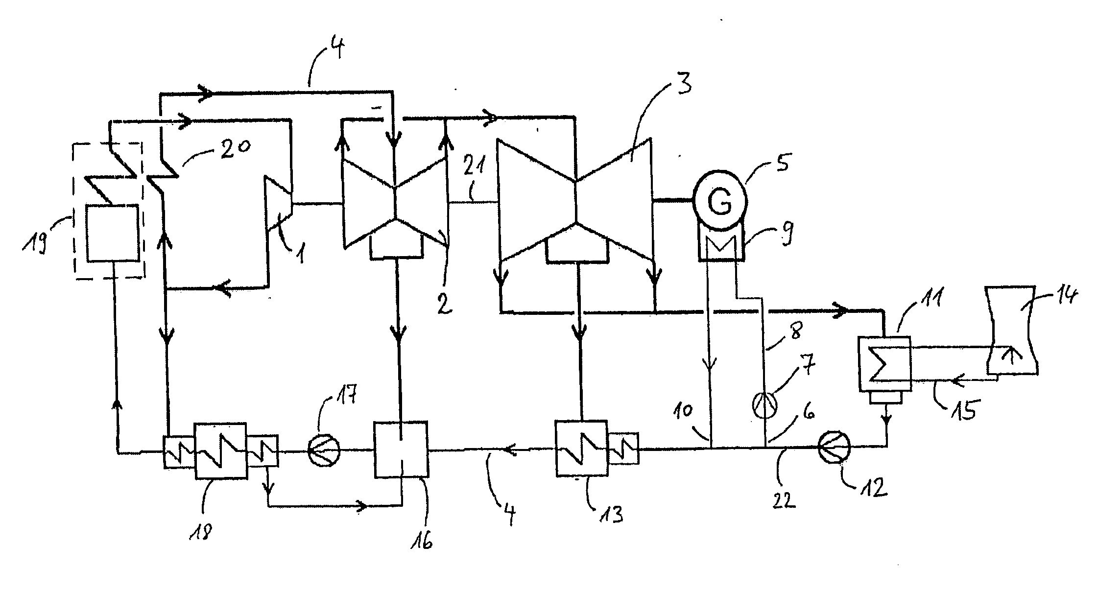
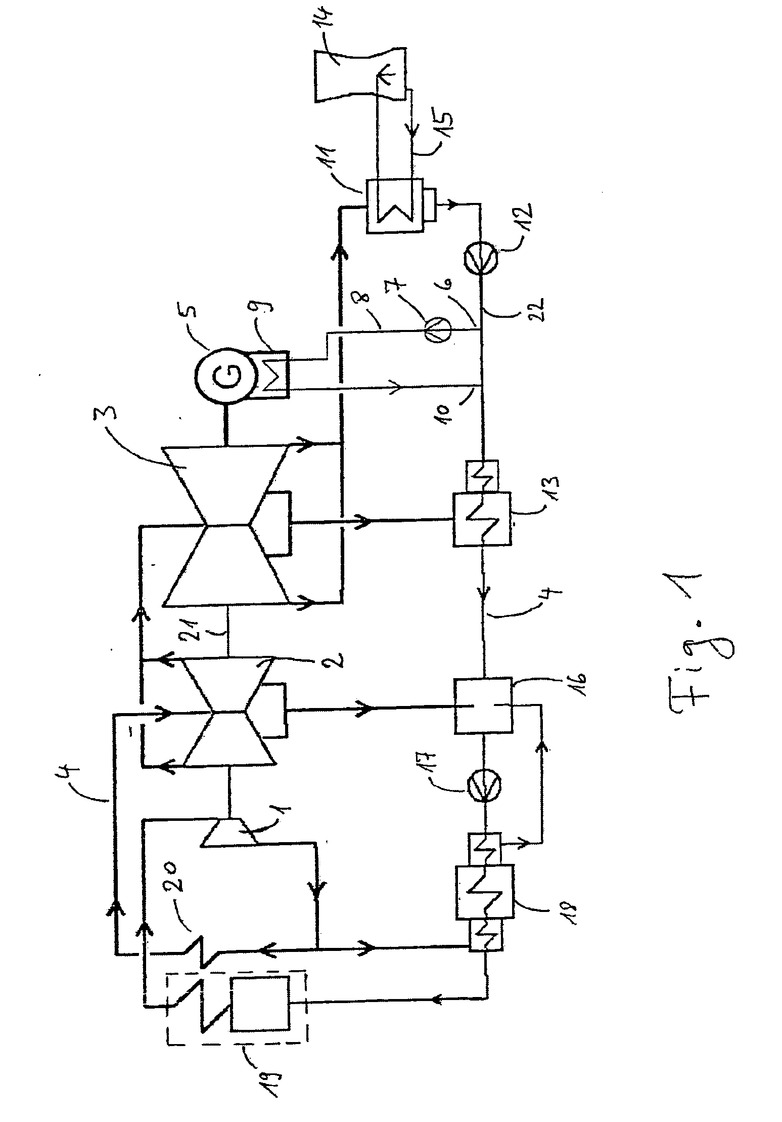
[0017] A preferred embodiment of the thermal power plant according to the present invention is shown in FIG. 1. The power plant comprises three turbines, namely a high pressure turbine 1, a medium pressure turbine 2 and a low pressure turbine 3, which are all mounted on a single drive shaft 21 connected to an electric generator 5. The turbines are operated by a water-steam-loop 4. The high pressure turbine 1 is supplied with highly pressurized hot steam from a steam raising unit 19. The steam expands to a certain extent in the high pressure turbine 1 and thereby causes the turbine and therewith the drive shaft 21 to rotate. The expanded steam exiting the high pressure turbine 1 is both of reduced pressure and of reduced temperature. Some of this steam is then diverted to a high-pressure pre-heater 18 arranged prior to the steam raising unit 19 in the water-steam-loop 4. The remaining portion of the steam is routed to a re-heater 20 from where it is forwarded to the medium-pressure t...


PUM


Abstract

The invention relates to a thermal power plant including a turbine (1, 2, 3) operated using at least one water-steam-loop (4), and a generator (5) driven by said turbine (1, 2, 3). According to the present invention, means (6, 7, 8, 9, 10) for cooling said generator (5) are provided, which means (6, 7, 8, 9, 10) are de signed for extracting condensate from said water-steam-loop (4), transporting it to said generator (5) and returning it into said water-steam-loop (4).

Description

FIELD OF THE INVENTION [0001] This invention relates in general to a thermal power plant including a turbine operated using at least one water-steam-loop, and a generator driven by said turbine. The thermal power plant referred to can e.g. be a conventional steam power plant, a combined gas and steam power plant or a nuclear power plant. BACKGROUND OF THE INVENTION [0002] Thermal power plants known in the prior art comprise a turbine, which is supplied with pressurized steam from a steam raising unit. The pressurized steam expands in the turbine and thereby causes the turbine to rotate. This rotational motion is transferred via a drive shaft to an electric generator, which generator converts the mechanical energy into electrical energy. The inevitable energy losses during the energy conversion in the generator lead to an undesirable heating of the generator. In order to avoid excessive generator temperatures, it is necessary to cool the generator during operation. In the prior art t...

Claims


Application Information

Patent Timeline
IPC IPC(8): F01K13/00
CPCF01K7/18F01K13/006F01K27/02
Inventor KAHLBAU, LUTZULM, WILFRED
Owner SIEMENS AG
Why Eureka
Try Eureka